Summary of Arduino Backlit LCD shield
This tutorial guides you through building a custom backlit LCD Arduino shield using an HD44780-compatible display, a Freetronics Protoshield Basic, a button, a 0.1 uF capacitor, header pins, and solid core wire. The project involves planning with schematics, testing contrast settings, and soldering components to create a functional interface driven by the LiquidCrystal library.
Parts used in the Arduino Backlit LCD Shield:
- Two line sixteen character backlit LCD (HD44780-compatible)
- Freetronics Protoshield Basic
- Button
- 0.1 uF capacitor
- Header pins
- Solid core thin wire for jumpers
In this tutorial learn how to make your own backlit-LCD Arduino shield.
Let’s see how simple it is to make your own Arduino LCD shield. Sure – you can just buy one, but where’s the fun in that?
Getting Started
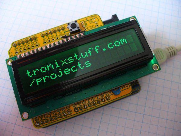
Our LCD is a two line, sixteen character backlit LCD. It has a typical HD44780-compatible interface, which makes it very easy to use with Arduino. The other parts required are laid out along with the LCD:
We have the LCD, a Freetronics Protoshield Basic, a button, a 0.1 uF capacitor and some header pins. We also need some solid core, thin wire to make jumpers.
Next is the plan – our schematic. Even for the smaller projects, this is a wise step. You can iron out the bugs before soldering. From experience with these backlit LCDs, there are two ways to wire them up. Either with a trimpot so you can adjust the display contrast, or without. With my example screen, the display was only clear with the trimpot turned all the way to one side, however your screen may vary.
Please note that the voltage for LCD backlights can vary, some are 5V, some are 3.3V. Check your data sheet and plan accordingly!
Consider the following schematics:
If you are making this circuit without the protoshield, the 0.1 uF capacitor is for decoupling, so place it between 5V and GND. It would be wise to test your LCD using the setup on pin 3 as shown in the second schematic. Then you will have a good idea about the display brightness and contrast. This was done with the usual breadboard setup, but not before soldering the pins into the LCD:
which allowed the LCD to slot into the breadboard nicely:
The brightness shown in the image above is satisfactory, so I measured the resistance between each of the outside pins of the trimpot and the center. The resulting resistance between the center and ground was around 15 ohms, so basically nothing. So for this LCD, there will not be any adjustments – and the full schematic above will be used (with LCD pin 3 going straight to GND).

The sketch to drive this LCD is quite simple, for example this will do:
For more information about using LCD modules with your Arduino, please refer to my series of Arduino tutorials.
For more detail: Arduino Backlit LCD shield
- What interface does the LCD use?
The LCD uses a typical HD44780-compatible interface which makes it easy to use with Arduino. - Can I make this circuit without a protoshield?
Yes, if making the circuit without the protoshield, place the 0.1 uF capacitor between 5V and GND for decoupling. - How do I determine the correct backlight voltage?
You must check your specific data sheet because backlight voltage can vary between 5V and 3.3V. - What is the best way to test the display before soldering?
Test your LCD using a breadboard setup on pin 3 to get an idea about display brightness and contrast. - Why might I not need a trimpot for my screen?
If the resistance between the center and ground of the trimpot is around 15 ohms, no adjustments are needed and pin 3 goes straight to GND. - Which library is required to drive this LCD?
You need the liquidCrystal library to execute the commands for the LCD unit. - How do I initialize the library in the code?
Initialize the library with the numbers of the interface pins using the command LiquidCrystal lcd(4,5,6,7,8,9). - What parameters define the LCD size in the setup function?
You must specify how many columns and rows are in the unit using lcd.begin(16, 2).