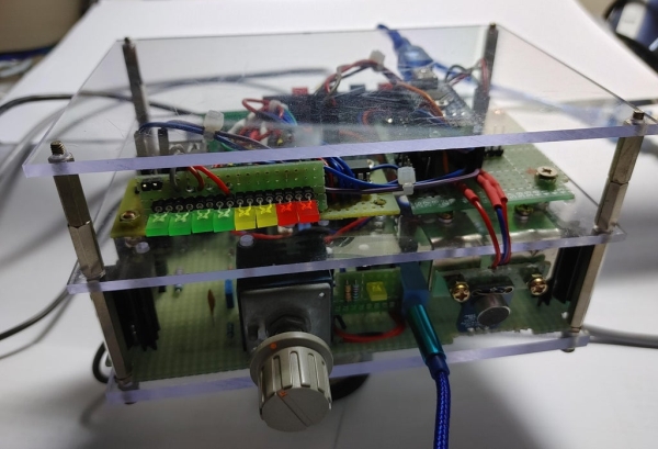
This is add-on of the audio amplifier project result which is introduced in other instructable. (https://www.instructables.com/PC-Speaker-Amplifier/)
Usually many types of sound level meters are directly connected with input (or rarely output) signal lines of amplifier.
But personally I’m thinking any electrical connections with amplifier circuit may surely degrade music playback quality by inserting some noises or causing any interference with audio signals.
Therefore, I’m prefer to use totally isolated sound level measuring method such as monitoring current fluctuation according to the changed intensity of audio signal.
To prove the idea, I made prototype device to detect current changes and turn the measurement result into visual effect.
I connected current measuring sensor (ACS712 hall effect current meter) to power supply line and interfacing it with LED indicator circuit.
Firstly this method seems very plausible before to actually measure current fluctuation according to the audio output differences from speaker.
But the result was disappointing as DC current change is a little bit small and current measurement usually lagging behind the dynamic audio signal fluctuations.
Therefore, visual indication which is following DC current change is very dull and unimpressive.
Due to the reason, I selected the Adafruit sound/noise measuring break-out board as alternative solution.
***
This is sound level meter using Arduino Nano and Adafruit Electret Capsule Microphone break-out which including MAX4466 amplifier IC chip.
As this breakout board and LED indicator circuit using totally separated power supply from the amplifier, personally wanted total isolation with audio signal can be possible.
The microphone breakout is receiving any sounds (or noises) at surrounding and amplifying it enough to produce voltage to be fed to Arduino.
Therefore, according to the sound level changes, output voltage quickly following and dynamically driving 8 LEDs indicator circuit.
Let’s look more detail on the circuit made.
Step 1: Sound Level Meter Schematics
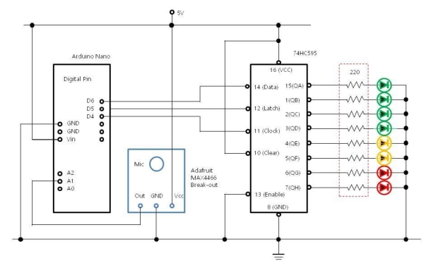
Overall circuit is consists with three major components such as Arduino Nano, Adafruit MAX4466 break-out board and 74HC595 Shift register IC.
The operation of sound level meter is as follows.
***
– Adafruit break-out board installed with ceramic microphone which detecting audio signal
– Detected very small audio signal (uV ~ mV) by microphone is amplified by MAX4466 IC and amplification ratio can be adjust by small VR attached to the break-out board
– Amplified audio signal voltage fed to the analogue input port A1 of Aduino nano (You can use any of analog port available)
– Received input voltage by Arduino is in range of (0.3 ~ 0.5V) and it’s my VR setting of Adafruit break-out board (When you setting the VR differently, output voltage range will be different from mine)
– According to the received present voltage level, sketch C-program driving 74HC595 to drive 8 LEDs up to certain level (Detail will be shown later when explaining sketch C-program)
***
When LEDs are driven directly without 74HC595, total 8 digital ports of Arduino should be used.
But only 3 control lines are necessary when shift register is used and that’s why 74HC595 is included to this circuit.
I will not explain shift register IC’s operational details as web contents are quite abundant in Internet.
You can see similar project example using 74HC595 in other instructable. (https://www.instructables.com/Disk-Usage-and-File-Download-Indicator/)
Step 2: Wiring Drawing
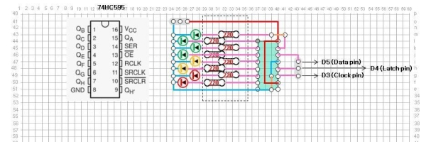
Wiring diagram is much simple as only single 74HC595 IC is connected with 8 LEDs.
Three (3) control lines (Data, Latch, Clock) are connected between 74HC595 and Arduino Nano.
Usually current limiting resistor (220ohm ~ 330ohm) is required between 74HC595 output pin and LED anode terminal.
Although my circuit is working without current limiting resistors, please use resistor still as the standard wiring method requires it.
Step 3: Parts
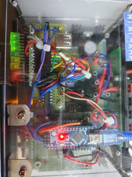
As the circuit is simple, used components are not many.
Adafruit MAX4466 board is not shown in the picture above as it attached and fixed on the front side.
The following break-out boards and electronic parts are used.
***
– Arduino Nano board
– Adafruit Electret Capsule Microphone break-out which including MAX4466 amplifier IC chip
– 74HC595 shift register IC
– Green LED x 4, Yellow LED x 2, Red LED x 2
– 16 IC pin head
– Universal PCB boards
– Jumper cables x 15
– Acrylic boards (15cm (W) x 10cm (D) x 3mm)
– Bolts and nuts (M3 size)
***
All components are mounted & fixed on acrylic board and mounted on the top of audio amplifier circuit board.
Step 4: Sketch C-program
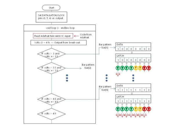
Sound level output is received from Adafruit code and stored into variable volts.
I’m used the same C-language sketch code posted on the Adafruit web-page without any modification.
As input voltage value is very small (0.3 ~ 0.49V), multiplying 10 to voltage value and storing the result to variable volts.
If volts is in range of 3.3 ~ 3.6, then char array bar[1] which storing value ‘B10000000’ is selected.
The bar[1] byte pattern ‘B10000000’ is transfer to 74HC595 shift register.
Afterward Latch command is activated and LEDs are turned on accordingly as shown in the picture above.
*** Code start
// Adafruit sound level checking parameter
const int sampleWindow = 50; // Sample window width in mS (50 mS = 20Hz)
unsigned int sample;
// Shift register control Arduino ports
int dataPin = 5; // Data pin of (14) 74HC595
int latchPin = 4; // Latch pin of (12) 74HC595 is connected to Digital pin 5
int clockPin = 3; // Clock pin (11) of 74HC595 is connected to Digital pin 6
// 8 LED turn on pattern
byte leds = 0;
char bar[9] = {
B00000000,
B10000000,
B11000000,
B11100000,
B11110000,
B11111000,
B11111100,
B11111110,
B11111111
};
void setup() {
// Set all the pins of 74HC595 as OUTPUT
pinMode(latchPin, OUTPUT);
pinMode(dataPin, OUTPUT);
pinMode(clockPin, OUTPUT);
Serial.begin(9600);
}
void loop() {
// Adafruit C-code start
unsigned long startMillis= millis(); // Start of sample window
unsigned int peakToPeak = 0; // peak-to-peak level
unsigned int signalMax = 0;
unsigned int signalMin = 1024;
double volts;
// collect data for 50 mS
while (millis() – startMillis < sampleWindow)
{
sample = analogRead(1);
if (sample < 1024) // toss out spurious readings
{
if (sample > signalMax)
{
signalMax = sample; // save just the max levels
}
else if (sample < signalMin)
{
signalMin = sample; // save just the min levels
}
}
}
peakToPeak = signalMax – signalMin; // max – min = peak-peak amplitude
double volt = (peakToPeak * 5.0) / 1024; // convert to volts
// Adafruit C-code end
volts = volt * 10;
// Serial.println(volts);
if (volts <= 3) {
leds = bar[0];
}
else if (volts > 3 && volts <= 3.3) {
leds = bar[1];
}
else if (volts > 3.3 && volts <= 3.6) {
leds = bar[2];
}
else if (volts > 3.6 && volts <= 3.9) {
leds = bar[3];
}
else if (volts > 3.9 && volts <= 4.1) {
leds = bar[4];
}
else if (volts > 4.1 && volts <= 4.3) {
leds = bar[5];
}
else if (volts > 4.3 && volts <= 4.6) {
leds = bar[6];
}
else if (volts > 4.6 && volts <= 4.9) {
leds = bar[7];
}
else if (volts > 4.9) {
leds = bar[8];
}
sound_level();
}
// Wirting byte LED turn on pattern to 74HC595
void sound_level() {
for (int i = 0; i < 8; i++) {
updateShiftRegister();
delay(10);
}
}
// Control command send to 74HC595 for LED turning on
void updateShiftRegister() {
digitalWrite(latchPin, LOW);
shiftOut(dataPin, clockPin, LSBFIRST, leds);
digitalWrite(latchPin, HIGH);
}
*** End of code
If you change testing condition of volts (e.g. if (volts > 4.3 && volts <= 4.6)) to other values, LED turning on pattern will be change.
When volts testing value is less than 3 (such as 2) and increased 0.4 in each step of if-else statement, LED will be turned on earlier from the lower sound level.
But LED turning on is quickly reaching up to highest level (e.g. 8th Red LED).
Therefore, you may need several trials of testing condition setting and modification to get proper LED turning pattern suite to your specific audio operation environment.
Step 5: Video of Sound Level Meter Operation
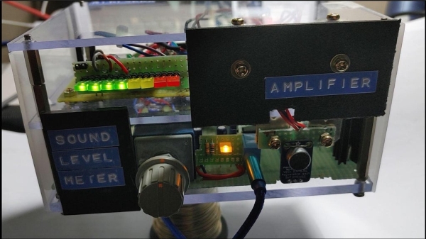
Sound Level Meter circuit is merged with
audio amplifier in a single acrylic box.
Also some face lifts are applied to the box by attaching side panels, filling gap with black acrylic board segment and applying several labels.
As microphone should be exposed for sensing sounds, Adafruit break-out board is not covered as shown in the picture above.
You can see video of the circuit operation in the link below.
***<Video Link>
https://drive.google.com/file/d/1cJDwM1vIHBfRoSrxT…
***
As shown in the video, LED turning on timing should be coordinated to the actual audio outputs from speakers to give dynamic and synchronized visual impression.
Therefore, choosing optimized volts (measured output voltage from Adafruit break-out board) testing condition is very important.
Source: Arduino Audio Sound Level Meter
