Summary of Arduino Assisted RC Truck/Car
Summary: The author retrofits a 1996 Stampede 2wd RC truck with an Arduino to add modern safety and convenience features like signal-loss cutoff, low-voltage cutoff, training speed modes, and lighting. The Arduino reads PWM servo signals from the RC receiver using pulseIn(), maps them to servo positions, and drives the ESC or servos. If the receiver signal times out, the Arduino forces throttle to neutral to prevent runaway. Example wiring, mounting suggestions, and complete sample code for signal cutoff are provided.
Parts used in the Arduino Assisted RC Truck/Car:
- RC Truck/Car (Stampede 2wd in the article)
- Arduino (Duemilanove used in the article)
- 3-pin female servo connector (servo lead)
- ESC (Electronic Speed Controller)
- RC receiver
- Servo(s)
- Breadboard or Protoshield (optional)
- Plastic enclosure or mounting hardware (recommended)
- Wires (for signal, 5V, and ground connections)
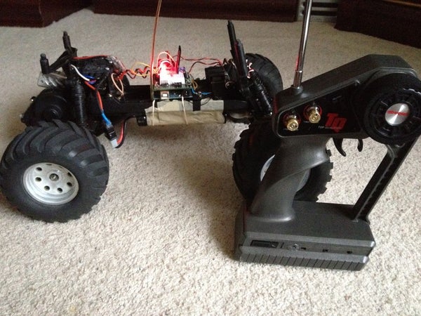
Recently I dusted off my 7 year old Stampede 2wd, designed in 1996. I got it for my 8th birthday. The truck was great, but it had a few caveats. For example, if the truck ran out of range, battery was low, or the transmitter batteries died on you, the truck would keep the throttle on the last position. Thanks to this accidental cruise (out of) control (See what I did there? 0_o), I accidentally drove my truck into a lake in my backyard!
The newer trucks have some safety features built in, or you can get additional aftermarket parts for your truck. I, however, decided to use an arduino, to make an ultimate computer assisted truck, that has many features of a newer truck. For example, Flashing or steady lighting, Low voltage Cutoff, Training modes (limited speed), Signal loss protection (Cuts off motor when signal is lost.) The list goes on and on!
After reading up on the inner workings of the truck, its quite simple, and it’s very inviting for an Arduino! Each channel controls a servo, which run at 5 volts, Arduino’s favorite voltage! The servos run off of PWM, Easily interpreted and controlled by an Arduino!
So far, here’s the only video I have of the vehicle: Anti Locking Brakes, And LCD telemetry!
Step 1: Materials!
The bare minimum for this build is quite simple!
You will need:
Your Truck/Car
Arduino, I chose a duemilinove.
3 pin female servo connector (Like the one on a regular servo)
Optional breadboard or Protoshield.
Step 2: Setup!
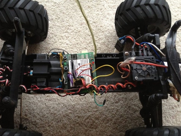
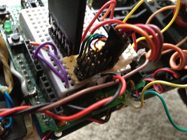
Connecting the Arduino to the truck is quite simple. The RC receiver outputs 5 volts, and a PWM servo signal.Using a 3 pin servo wire, you can connect the bare wire ends to the Arduino, Ground goes to ground, 5 volts goes to 5 volts on the Arduino, Signal goes to any digital pin on the Arduino. Tadaa! Now, connect the ESC cable the same way, and make sure to use a digital pin.
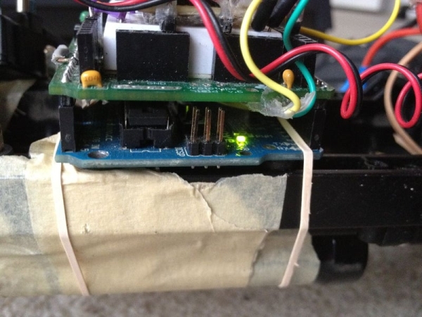
As far as mounting the arduino to the truck, I recommend using some sort of plastic enclosure to seal out water, dust, and dirt. For prototyping, I used some open source hardware, RUBBER BANDS!
Step 3: Servo Reading! With Signal Cutoff!
Reading the servo signals that come off of your RC receiver is simple.. ish…
Using pulseIn(), you can time how long the pulse coming out of your receiver. Using the output of Arduino’s Servo signals, I was able to calibrate the readings.
here is the code to read a signal. note, 520 and 2370 are microsecond values that are used to calibrate the readings. I used the output from Arduino’s Servo Library to calibrate it, and it worked fine. PWMpin is an input from the RC receiver. 20000 is a microsecond value that is used as a timeout feature. If the timeout limit is reached, we know that we aren’t getting signals from the Transmitter, and we can later use it to cutoff the motors.
RCinput = pulseIn(PWMpin, HIGH, 20000);
ServoVal = map(RCinput, 520, 2370, 0, 180);
after that, we do some data analysis! Note, ThrottleServo is an output on which the ESC’s input is connected to an Arduino pin. Pin 13 is an output used to indicate an error.
if(RCinput== 0) { // Signal timed out!
digitalWrite(13, HIGH); // ALERT!
ThrottleServo.write(97); // Go to neutral throttle position
}
}
else{
digitalWrite(13, LOW);
ThrottleServo.write(ServoVal); // Repeat the data to the truck’s ESC
Serial.print(” PulseMicros “); // This part is used to debug the values for calibration
Serial.print(RCinput);
Serial.print(” ServoRead “);
Serial.println(ServoVal);
}
Step 4: Final Code for Signal Cutoff
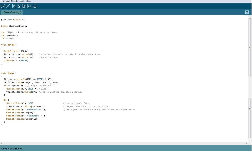
#include <Servo.h>
Servo ThrottleServo;
int PWMpin = 2; // connect RC receiver here.
int ServoVal;
int RCinput;
void setup()
{
Serial.begin(9600);
ThrottleServo.attach(9); // attaches the servo on pin 9 to the servo object
ThrottleServo.write(97); // go to nuetral
pinMode(13, OUTPUT);
}
void loop()
{
RCinput = pulseIn(PWMpin, HIGH, 20000);
ServoVal = map(RCinput, 520, 2370, 0, 180);
if(RCinput== 0) { // Signal timed out!
digitalWrite(13, HIGH); // ALERT!
ThrottleServo.write(97); // Go to neutral throttle position
}
else{
digitalWrite(13, LOW); // everything’s fine.
ThrottleServo.write(ServoVal); // Repeat the data to the truck’s ESC
Serial.print(” PulseMicros “); // This part is used to debug the values for calibration
Serial.print(RCinput);
Serial.print(” ServoRead “);
Serial.println(ServoVal);
}
}
Source: Arduino Assisted RC Truck/Car
- What is the minimum hardware needed to build the Arduino assisted RC truck?
Your Truck/Car, an Arduino (Duemilanove used), and a 3-pin female servo connector; breadboard or Protoshield is optional. - How do you connect the RC receiver to the Arduino?
Use a 3-pin servo wire: ground to Arduino ground, 5V to Arduino 5V, and signal to any digital pin on the Arduino. - How does the Arduino detect signal loss from the transmitter?
It uses pulseIn() with a timeout (20,000 microseconds); if pulseIn returns 0, the code treats it as signal timed out. - What does the Arduino do when the receiver signal times out?
It sets an alert output (digital pin 13 HIGH) and writes the throttle servo to neutral (ThrottleServo.write(97)). - How are PWM input values converted to servo positions?
The code maps pulseIn microsecond readings (calibrated between 520 and 2370) to 0–180 using map(). - Which Arduino pin is used to drive the throttle servo in the example?
In the example code the throttle servo is attached to pin 9. - How can the Arduino be mounted to the truck for protection?
The article recommends using a plastic enclosure to seal out water, dust, and dirt; rubber bands were used temporarily for prototyping. - Does the article provide example code for signal cutoff?
Yes, the article includes full example code demonstrating reading the receiver, mapping values, and enforcing a neutral throttle on timeout.