Summary of Arduino and L293D Robot ( Part 1 )
This article introduces the first part of a series on building an Arduino-based Line Follower Robot. It details the assembly of a basic robot using an Arduino Board and an L293D motor driver chip to control two DC motors. The guide provides specific wiring instructions for connecting power sources, grounds, and control signals between the components to enable motor operation.
Parts used in the Arduino and L293D Robot:
- Arduino Board
- Breadboard
- L293D Chip
- Two Motors
- 9 Volt Battery
- 6 Volt Battery Pack
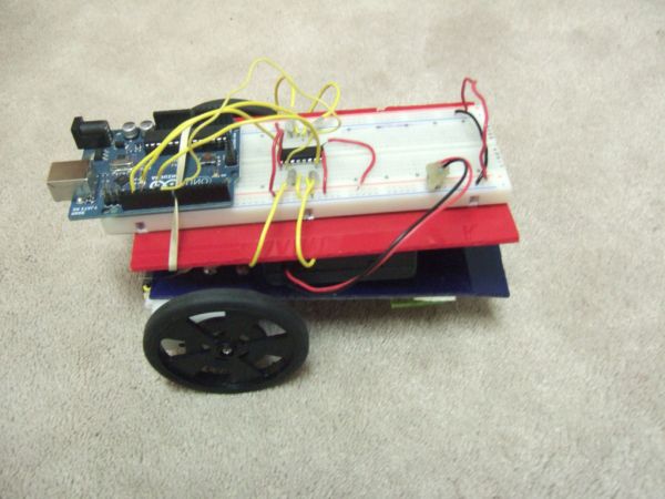
Here is part 1 of the Arduino and L293D Robot.This is part of a series of instructables leading to a Line follower Robot.
This is a basic Robot made by controlling two motors via the L293D chip through an Arduino Board.
I have done this project in the past with similar set up just not with an Arduino Board.
Do let me know what you think of this project and if I made any mistakes.
Step 1: Parts
Breadboard
L293D Chip
Two Motors
9 Volt Battery
6 Volt Battery Pack
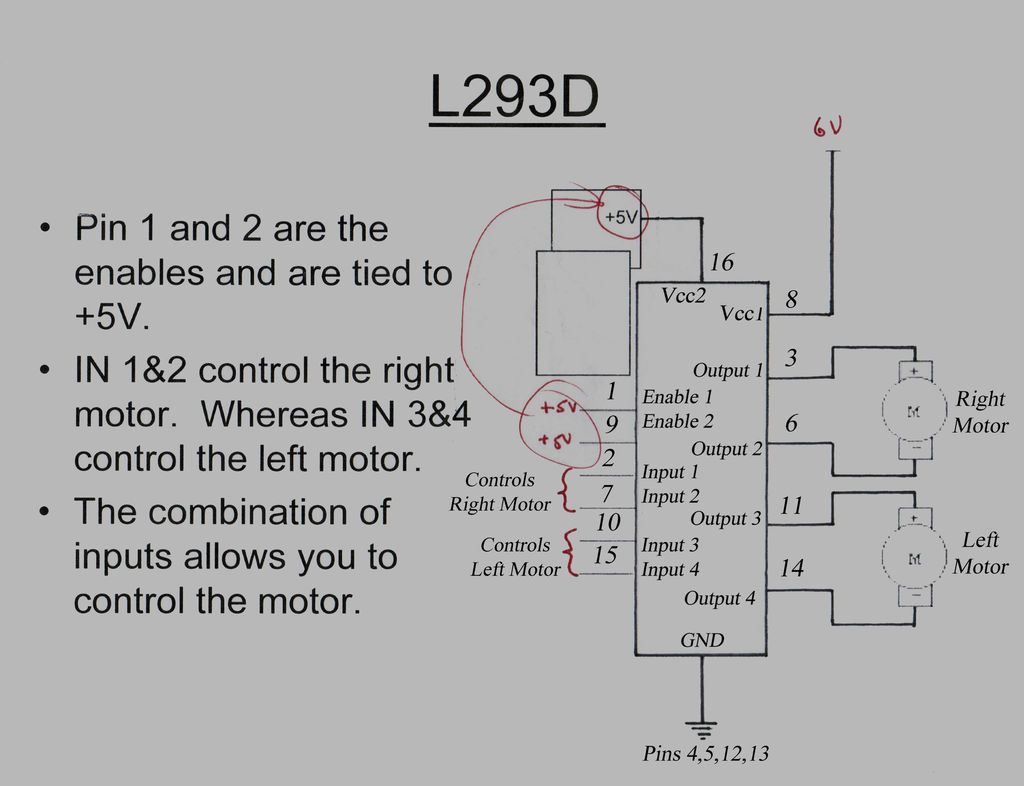
Step 2: Wiring the L293D Chip
Pin 4 ,Pin 5,Pin 12 and Pin 13 from L293D Chip Connect to Ground (Negative On Breadboard)
Pin 1,Pin 9 and Pin 16 from L293D Chip Connect to 5 Volts (Positive On Breadboard)
Pin 8 from L293D Chip Connects to 6 Volts (Positive On Breadboard)
Pin 3 from L293D Chip Connects to Right Motor
Pin 6 from L293D Chip Connects to Right Motor
Pin 11 from L293D Chip Connects to Left Motor
Pin 14 from L293D Chip Connects to Left Motor
Output pins on Arduino to control Right Motor :
Pin 2 from L293D Chip Connects to Output Pin on Arduino
Pin 7 from L293D Chip Connects to Output Pin on Arduino
Output pins on Arduino to control Left Motor :
Pin 10 from L293D Chip Connects to Output Pin on Arduino
Pin 15 from L293D Chip Connects to Output Pin on Arduino
Step 3: Connecting the Motors to L293D Chip
Pin 3 from L293D Chip Connects to Right Motor
Pin 6 from L293D Chip Connects to Right Motor
Pin 11 from L293D Chip Connects to Left Motor
Pin 14 from L293D Chip Connects to Left Motor
Step 4: Connecting the pins to 5 Volts and Ground
Pin 4 ,Pin 5,Pin 12 and Pin 13 from L293D Chip Connect to Ground (Negative On Breadboard)
Pin 1,Pin 9 and Pin 16 from L293D Chip Connect to 5 Volts (Positive On Breadboard)
Pin 8 from L293D Chip Connects to 6 Volts (Positive On Breadboard)
Step 5: Output pins on Arduino to control the Motors
Output pins on Arduino to control Right Motor :
Pin 2 from L293D Chip Connects to Output Pin on Arduino
Pin 7 from L293D Chip Connects to Output Pin on Arduino
Output pins on Arduino to control Left Motor :
Pin 10 from L293D Chip Connects to Output Pin on Arduino
Pin 15 from L293D Chip Connects to Output Pin on Arduino
For more detail: Arduino and L293D Robot ( Part 1 )
- What is this project?
This is a basic robot made by controlling two motors via the L293D chip through an Arduino Board. - How do I connect Pin 4 of the L293D Chip?
Pin 4 connects to Ground (Negative On Breadboard). - Which pins on the L293D Chip connect to the Right Motor?
Pin 3 and Pin 6 from the L293D Chip connect to the Right Motor. - Can I use this setup without an Arduino Board?
The author has done this project with a similar setup but not with an Arduino Board previously. - What voltage does Pin 8 of the L293D Chip require?
Pin 8 connects to 6 Volts (Positive On Breadboard). - How many batteries are listed in the parts section?
The parts list includes a 9 Volt Battery and a 6 Volt Battery Pack. - Which pins on the L293D Chip connect to the Left Motor?
Pin 11 and Pin 14 from the L293D Chip connect to the Left Motor. - Where do Pin 1, Pin 9, and Pin 16 connect?
These pins connect to 5 Volts (Positive On Breadboard).