Summary of Arduino 7 segment Displays Digital Clock With Charlieplexing LEDs
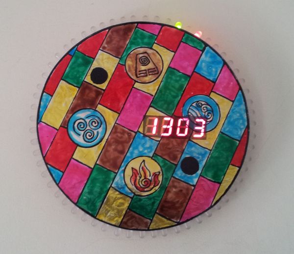
This project is a custom digital clock featuring a 24-hour seven-segment display and an analog-style face created with 60 bi-colored LEDs using Charlieplexing. The author utilized an Atmega168 microcontroller with a burned Arduino bootloader, driven by a DS1307 RTC for accurate timekeeping independent of power cuts. The design combines standard logic chips (4511, 74HC139) for the digital readout while manually etching concentric PCB tracks for the LED array, offering a comprehensive learning experience in embedded systems and PCB fabrication.
Parts used in the Digital Clock Project:
- Atmega168 microcontroller
- CD4511BE BCD-to-7-segment decoder driver
- 74HC139N dual 2-to-4 line decoder/demultiplexer
- DS1307 Real-Time Clock chip
- 7805 voltage regulator
- Standby Arduino board for burning bootloader
- Four common cathode 7-segment displays
- 16MHz crystal oscillator
- 32.768kHz watch crystal
- 9V battery and plug
- 3V coin cell battery with holder
- Push button switch
- Ceramic capacitors (22pf and 100nf)
- Electrolytic capacitor (100uf)
- Resistors (2.2 Kohms and 10 Kohms)
- 60 5mm bi-colored LEDs
- Male headers and jumpers
- PCB board
- Connecting wire
- Soldering iron and solder
- 2mm thick plexiglass
- Glass paint kit
- Aluminium foil
- Nut and bolt
- Hanging hook
- PCB drill and glue gun
This is my second instructable. I just had a mood of making a digital watch. But wanted to make it a learning process. I already had a sanguino i could have easily used that Atmega644 chip. it would have been more than enough. But i wanted to try burning a Arduino bootloader and see if i could make it work. Well i did. I used a Atmega168 for this project.
I used 4 seven segment displays to display time in 24hr format. Here ii experimented with common anode and common cathode. Now i wanted to use other chips too and not just the Arduino which would have been the easier option. The chips i experimented with are 74LS47, 74HC154, 74HC595 ,4511 and 74HC139. The final compatible combination was common cathode with 4511 and 74HC139.
I used a RTC chip DS1307 to feed the time to the Arduino. I initially wanted to use millis() function in Arduino but it is not that accurate. Using RTC not only saved long coding but also has an added advantage of keeping the time in case the external supply is cutoff. It uses a 3v battery to do this.
Now I have used LEDs to point the time as minute and hour hands would do in an anolog clock. 60 Bi-coloured LEDs total which work on Charlieplexing.
Well if you are interested onwards you go.
Step 2: Circuit
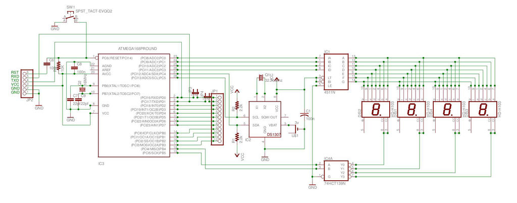
I have made the circuit in Eagle but sadly I am not that proficient in using the software (Which is next on my “TO LEARN” list) so I didn’t make the board. I have attached the schematic i made on Eagle. U can use it to make the board.
I used Express PCB to create the PCB. I have also attached this .pcb file here. You can either print this file directly and make a pcb from a copper clad or build a board from Eagle and get it made professionally.
NOTE:
1) In express PCB file I’ve used JMP at some places. It means you have to use wires to short the two pads. This was necessary since i used a single sided PCB. Confirm where to connect wires from the circuit diagram.
2) At digital pin 0 and 1 i have used jumpers. This is VERY IMPORTANT as the LEDS have to be disconnected from these points as they are RX and TX pins. LEDs if connected while uploading the program will use up the voltage and hinder the uploading. I learnt it the hard way. So i made changes afterwards. So while uloading Remove the jumpers thus effectively disconnecting them from LEDs and replace them once the uploading is done.
 Clock(Eagle).sch522 KB
 Clock(Eagle).pdf22 KB
Step 3: LED circuit
The PCB that i have built does not include the Charlieplexing LED circuitry. I made the 12 round tracks using a waterproof marker and compass.
IMPORTANT POINTS TO REMEMBER
1) The outermost track is 16cm in diameter.
2) The innermost track is about 12.5cm in diameter.
3) These diameter specifications you can vary as long as the total width of 12 concentric tracks does not exceed the length of the LED leads or you won’t be able to solder properly.
4) The actual placement of the LEDs was done manually i.e without the help of computer. I found it easier and faster.
5) Do not make any hole pads for the LEDs before etching. Just be sure to make the concentric tracks thick enough so after drilling they wont get disconnected completely.
Now etch the PCB. See the Image for what it should look like.
CD4511BE + Holder (CMOS BCD-TO-7-SEGMENT LATCH DECODER DRIVER)
74HC139N + Holder (Dual 2-to-4 line decoder/demultiplexer)
DS1307 + Holder (DS1307 64 x 8, Serial, I C Real-Time Clock)
7805
Standby Arduino board to Burn bootloader in Atmega168 (optional if Already hav a chip with Arduino bootloader in it)
Breakout board + USB wire
Common Anode 7 segment display (4)
16Mhz crystal
32.768 Khz watch crystal
9v battery + Plug
3v coin cell +Holder
Push button switch (Reset Arduino)
22pf ceramic capacitor (2)
100nf ceramic capacitor (3)
100uf electrolytic capacitor (2)
2.2 Kohms resistor (2)
10 Kohms resistor
5mm Bicolour LED (60) (There are different types see further for more information)
Male headers
Two Jumpers
PCB
Connecting wire
Soldering iron
Solder
2mm thick Plexiglass
Glass paint kit
Aluminium foil
3/4th inch Nut and Bolt
Hook to hang by a nail (I made one fron plexiglass pieces)
PCB drill
Glue gun
For more detail: Arduino 7 segment Displays Digital Clock With Charlieplexing LEDs
- Why was the DS1307 RTC chip chosen over the millis() function?
The DS1307 provides greater accuracy than millis() and maintains the time even when the external power supply is cut off. - What is the specific requirement for digital pins 0 and 1 during programming?
You must remove the jumpers connecting the LEDs to these pins while uploading the program because they are RX and TX pins used for communication. - Which combination of chips was found to be compatible for the final project?
The final compatible combination uses common cathode displays with the 4511 and 74HC139 chips. - How many LEDs were used and what technique allows them to work efficiently?
60 bi-colored LEDs were used, and they operate using a technique called Charlieplexing. - What are the diameter specifications for the concentric LED tracks?
The outermost track should be 16cm in diameter, while the innermost track is about 12.5cm in diameter. - Why did the author choose not to use the Sanguino board despite having the chip?
The author wanted to use the project as a learning process to try burning an Arduino bootloader onto an Atmega168 chip instead of using a pre-configured setup. - What precaution should be taken regarding hole pads for LEDs before etching the PCB?
Do not make any hole pads for the LEDs before etching; instead, ensure the concentric tracks are thick enough to prevent disconnection after drilling. - What does JMP mean in the Express PCB file?
JMP indicates that you need to use wires to short two pads together, which was necessary because a single-sided PCB was used.