Summary of Aquarium Management System
This article details the construction of a homemade Aquarium Management System using an Arduino Uno. The project automates fish feeding, monitors water temperature and level, controls lighting based on ambient light, and manages water pumps. It integrates sensors like ultrasonic and DS18B20 with actuators such as servos and relays to create a fully functional smart aquarium controller housed in a custom box.
Parts used in the Aquarium Management System:
- Arduino Uno
- Ultrasonic Sensor
- LCD (16x2)
- Potentiometer (10k)
- Servo motor
- 5V 2 Channel Relay
- Water Temperature Sensor
- Jumper Cables
- Photoresistor
- Water Pump Horizontal Type
- Resistors (2.2k ohms, 220 ohms, 1k ohms, 4.7 ohms)
- 6V Rechargeable Battery
- White Led Diode in Plexiglass
- LED Diode
- Arduino Box
- Water Pump Hose
- CSA Cable Assy LL83498 AWM Ribbon Connector
- DS Cables LIYCY 8x0.5 mm2 Flame Retardant
- RVVB 2x1.5 mm2
- KCD11-101 On/Off Switch
- Magnesium Tablet Box
- Transistor 7805
- Aquarium
- Big 10 Litters Water Bottle
- Metal Box
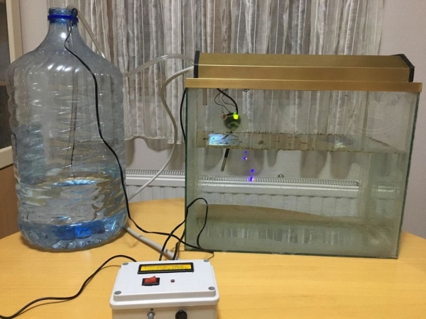
As my first project with Arduino, I would like to share how we can make a homemade Aquarium Management System. If you want your fish to be fed automatically and if you want to check the aquarium status like temperature, water level etc., this project might help you.
Step 1: The Components
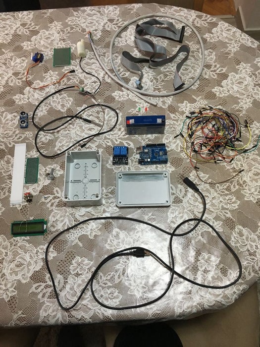
Here we are going to list all the components that are needed for this project.
- Arduino Uno
- Ultrasonic Sensor
- LCD (16×2)
- Potentiometer (10k)
- Servo motor
- 5V 2 Channel Relay
- Water Temperature Sensor
- Jumper Cables
- Photoresistor
- Water Pump Horizontal Type
- 1x 2.2k ohms, 1×220 ohms, 1x1k ohms, 1x 4.7 ohms Resistors
- 6V Rechargeable Battery
- 4x White Led Diode in Plexiglass
- 2x Led Diode
- Arduino Box
- Water Pump Hose
- CSA Cable Assy LL83498 AWM Ribbon Connector
- DS Cables LIYCY 8×0.5 mm2 Flame Retardant
- RVVB 2×1.5 mm2
- KCD11-101 On/Off Switch
- Magnesium Tablet Box
- Transistor 7805
- Aquarium
- Big 10 Litters Water Bottle
- Metal Box (for the ultrasonic, servo)
Step 2: Box Cutting and LCD Mounting With Photoresistor and Switch
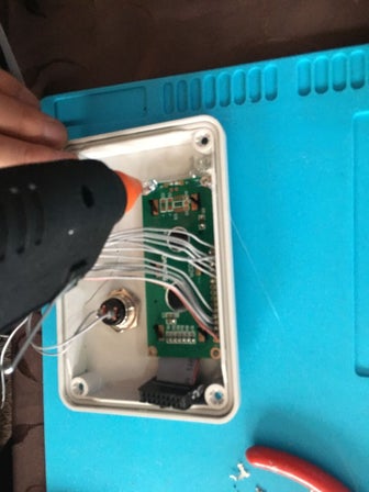
Firstly, we measure the length of the LCD which in our case is 7×2.5 cm so it can fit on the front of the box. Later we measure the switch button (2×1.3 cm) and the photoresistor and we add them on the front of the box.
Afterwards, on the one side of the box we drill several holes, 2 for the Arduino, 1 for the Water Temperature sensor, 1 for the Water Pump and 1 for the DS Cable. These cables later are connected in a metal box which is over the aquarium. On another side we drill 2 holes, one for the potentiometer and one for the power supply.
Next we cut the ribbon connector from the both sides, like plain wires, in order to connect them with the Arduino on the other sides and the LCD, photoresistor and potenciometer on the other side. The wiring from the ribbon to the Arduino is like this:
- 1-st wire from ribbon with VSS on LCD and with GND on Arduino
- 2-nd wire from ribbon with VDD on LCD and with VCC(5v) on Arduino
- 3-rd wire from ribbon with R0 on LCD and Potentiometer(middle pin)
- 4-th wire from ribbon with RS on LCD and digital pin 5 on Arduino
- 5-th wire from ribbon with RW on LCD and GND on Arduino
- 6-th wire from ribbon with E on LCD with digital pin 4 on Arduino
- 7-th wire from ribbon with D4 on LCD with analog pin 2 on Arduino
- 8-th wire from ribbon with D5 on LCD with analog pin 3 on Arduino
- 9-th wire from ribbon with D6 on LCD with analog pin 4 on Arduino
- 10-th wire from ribbon with D7 on LCD with analog pin 5 on Arduino
- 11-th wire from ribbon with A on LCD + 2.2k Resistor with VCC(5v) on Arduino
- 12-th wire from ribbon with K on LCD with GND on Arduino
- 13-th wire from ribbon with VCC on photoresistor with VCC on Arduino
- 14-th wire from ribbon with GND on photoresistor with 1.1k resistor + GND + analog pin 1 on Arduino (the GND wire and pin wire from Arduino are together soldered with the resistor which is connected with the ribbon wire)
All the components on the front of the box are glued with glue gun.
Note: All the VCC wires from all modules are soldered on one wire that goes in the VCC pin on the Arduino. Same goes for the GND wires from all modules.
Step 3: Connecting the Arduino With Relay Shield, Pump and LEDs
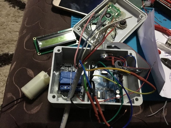
At first, we need to connect the relay with the Arduino. The VCC from relay goes to VCC on Arduino, GND from relay goes to GND on Arduino, IN1 pin from relay with digital pin 10 on Arduino and IN2 with digital 2 on Arduino.
Next we are going to connect the water pump to the first relay with the switch, and the LEDs for the temperature signaling to the second relay.
The first pin from the switch is connected with the VCC pin on the power jack, while the other pin is connected to the input pin of the transistor. The GND pin from the power jack, the GND pin from the transistor and the GND wire from the pump are soldered together. The VCC wire from the pump is connected with the NO pin from the first relay, while the output pin from the transistor is connected to the COM pin on the relay.
Since the LEDs are inside the aquarium, and the Arduino is on the side, we will need long wires to connect them. That’s where the DS Cable LIYCY 8×0.5 mm2 Flame Retardant comes in play. That cable has 8 wires in it, so we connect 2 of them with LED’s anodes respectively. Those wires have to be connected to the second relay, so the wire that is connected with the green LED is connected on the NC pin from the second relay, while the wire from the red LED is connected with the NO pin from the second relay. The LEDs cathodes are soldered together with 220 ohm resistor and 1 wire(GND) from the cable and together are connected with the Arduino’s GND. On COM pin on the second relay comes VCC from Arduino.
Step 4: Connecting the Other Sensors
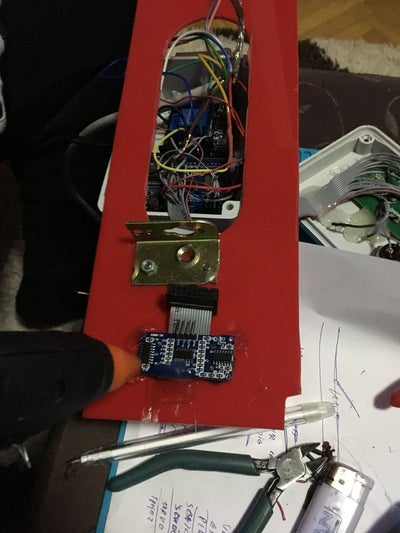
As we can see from the pictures, we have a red plastic board with hole in it which is a part of metal box that sits above the aquarium. In that hole, the Magnesium Tablet Box with the servo will rotate from time to time to feed the fish. The LED diodes in plexiglass is glued on the board so when it becomes dark, via the photoresistor it will activate. The other sensor on the board is the ultrasonic sensor, and through the hole of the board, the water temperature sensor will go in the water.
First, we will start with connecting the water temperature sensor with the Arduino. Since we drilled a hole on the Arduino’s box (check images from previous parts), we wont need extra wires to connect. The GND wire from the sensor goes to the GND pin on the Arduino, the VCC wire from sensor is connected with VCC pin and the data wire from the sensor is connected with the digital pin 8 on the Arduino. However, the data wire is also connected with the VCC wire from the sensor, soldered together with 4.7k ohms resistor.
Next is the ultrasonic sensor. This sensor is connect via 4 wires from the DS Cable (check previous part). The VCC wire is connected with VCC from Arduino and the VCC pin from the sensor. The GND wire is connected with the GND from Arduino and GND from the sensor. The remaining 2 wires are for the Echo and Trigger pin from the sensor. The Echo pin is connected on digital pin 7 on the Arduino, and the Trigger pin is connected on digital pin 6 on the Arduino via the wires respectively. However, we need to drill 2 holes so the ultrasonic’s “eyes” will point towards the water.
Afterwards is the servo motor. We will take out the servo’s rotating cap and we will replace it with the Magnesium Box cap. The connecting for the servo is simple. The VCC wire from the DS Cable is connected with the servo’s VCC wire, the GND wire from the cable is connected with GND wire from the servo, and the data wire from the servo is connected with the digital pin 9 on the Arduino via one of the wires left.
At last it comes the LED diodes in plexiglass. Techically, there are 4 LEDs in the plexiglass. But here we won’t need a resistor. In here, the anodes from the LEDs are soldered with one of the remaining wires of the DS Cable, which at the end is connected to digital pin 12. The kathodes are soldered with the GND wire from the cable together, and connected with the GND pin on the Arduino.
Step 5: Conclusion
Code:
include
include
include
include
//digital pin 8 for data for DS18B20 water temperature sensor
define ONE_WIRE_BUS 8
//digital pin 10 for relay1
define RELAY1 10
//digital pin 2 for relay2
define RELAY2 2
OneWire oneWire(ONE_WIRE_BUS);
// initialize the library by associating any needed LCD interface pin
// with the arduino pin number it is connected to
const byte rs = 5, en = 4, d4 = 16, d5 = 17, d6 = 18, d7 = 19;
byte trigPin = 6; // Trigger
byte echoPin = 7; // Echo
byte servoPin = 9; // Servo
byte light = 12; // Light
byte photocellPin = 1; //Photoresistor (analog pin 1)
Servo servo;
LiquidCrystal lcd(rs, en, d4, d5, d6, d7);
DallasTemperature sensors(&oneWire);
int i=0;
int val = 0; //analog value from photoresistor
int cm; //water level distance in cm
float Celsius = 0; // Water temperature
int servoAngle = 0; // Servo angle
unsigned long lastOccur = 0; // last time the servo was called (in milliseconds)
unsigned long current; // keep track of current time (in milliseconds)
void setup(){
Serial.begin(9600);
// set up the LCD’s number of columns and rows:
lcd.begin(16,2);
pinMode(trigPin, OUTPUT);
pinMode(echoPin, INPUT);
servo.attach(servoPin);
pinMode(RELAY1, OUTPUT);
digitalWrite(RELAY1, HIGH);
pinMode(RELAY2, OUTPUT);
digitalWrite(RELAY2, HIGH);
pinMode(light, OUTPUT);
}
void loop(){
//Check time (used as timer for the servo)
current = millis();
//Read the value from the analog pin from the photoresistor
val = analogRead(photocellPin);
//Calculate the temperature in celsius
Celsius = calcTemp();
// Convert the time into a distance
cm = ultrasonic_distance();
// Print the temperature and water level
printLCD(cm,Celsius);
//Activate pump if water level is less than 18 cm
if(cm > 18){
pump();
}
// Activate heater if temperature is below 22 degrees celsius
if(Celsius < 22){
heat();
}
// Activate light
if(val <= 412){
digitalWrite(light, HIGH);
}
else{
digitalWrite(light, LOW);
}
//timer 30s
if(current – lastOccur >= 30000){
callServo();
lastOccur=millis();
}
}
float calcTemp() {
sensors.requestTemperatures();
// returns the temperature in celsius
return sensors.getTempCByIndex(0);
}
int ultrasonic_distance(){
// Clears the trigPin
digitalWrite(trigPin, LOW);
delay(0.002);
//Sets the trigPin on HIGH state for 10 micro seconds
digitalWrite(trigPin, HIGH);
delay(0.01);
digitalWrite(trigPin,LOW);
return calcDistanceInCm(pulseIn(echoPin, HIGH));
}
int calcDistanceInCm(long dur){
//divide by 29.1 or multiply by 0.0343
return (dur/2)*0.0343;
}
void heat(){
delay(1000); // wait 1 second
digitalWrite(RELAY2, LOW); // turn on relay2
delay(5000); //wait for 5 seconds
digitalWrite(RELAY2, HIGH); // turn off relay2
delay(1000); // wait 1 second
}
void pump(){
delay(1000); //wait 1 second
digitalWrite(RELAY1, LOW); // turn on relay1
delay(20000); // wait 20 seconds
digitalWrite(RELAY1, HIGH); // turn off relay1
delay(1000); // wait 1 second
}
void printLCD(int cm, float temp){
lcd.clear();
// set the cursor to column 0, line 0
// (note: line 0 is the first row, since counting begins with 0):
lcd.setCursor(0, 0);
lcd.print(“Distance: “);
//print the water level in cm
lcd.print(cm);
lcd.print(“cm”);
lcd.setCursor(0, 1);
lcd.print(“Temperature:”);
//print the temperature in celsius
lcd.print((int)temp);
lcd.print((char)223);
lcd.print(“C”);
delay(1000)
}
void callServo(){
for(i=0;i<2;i++){
for(servoAngle = 0; servoAngle < 180; servoAngle++){ // move the micro servo from 0 degrees to 180 degrees
servo.write(servoAngle);
delay(7); // servo start speed (faster)
}
delay(2000);
for(servoAngle = 180; servoAngle > 0; servoAngle–){ // now move back the servo to 0 degrees
servo.write(servoAngle);
delay(10); //servo back speed (slower)
}
}
}
Source: Aquarium Management System
- How is the photoresistor connected to the Arduino?
The GND wire from the photoresistor connects to a 1.1k resistor which is then soldered to the GND and analog pin 1 on the Arduino. - What digital pins are used for the relay connections?
IN1 connects to digital pin 10 and IN2 connects to digital pin 2 on the Arduino. - How does the system determine when to turn on the lights?
The system activates the light if the photoresistor value is less than or equal to 412. - At what water level does the pump activate?
The pump activates if the calculated water distance is greater than 18 cm. - When does the heating function engage?
The heater turns on if the water temperature is below 22 degrees Celsius. - How often does the servo motor feed the fish?
The servo motor is called every 30 seconds based on the timer logic in the code. - Which cable is used to connect the LEDs inside the aquarium?
The DS Cable LIYCY 8x0.5 mm2 Flame Retardant is used to connect the internal LEDs to the Arduino. - What resistor value is used with the water temperature sensor data wire?
A 4.7k ohm resistor is soldered between the data wire and the VCC wire of the sensor.