Summary of Another Arduino Traffic light
This article details a DIY Arduino traffic light project designed with realistic timing, addressing the issue of existing online examples being too fast. The author modified code to achieve proper operation and documented the wiring and components used for two sets of traffic signals (red, yellow, green) on a breadboard.
Parts used in the Arduino Traffic Light:
- Arduino
- Breadboard
- 6 - 270 ohm resistors
- 2 - Red LED
- 2 - Yellow LED
- 2 - Green LED
- Wires
After working with the arduino and not knowing what the heck I’m doing I made Another simple traffic light. I looked around the web to find one that looks about normal and came across none. They seemed too fast. So, I found and modded some code to make this work. The coding is pretty simple.
Step 1: The Parts
1 – Arduino (Obvious)
1 – Breadboard
6 – 270 ohm resistors
2 – Red LED
2 – Yellow LED
2 – Green LED
Misc. – Wires and Patients.
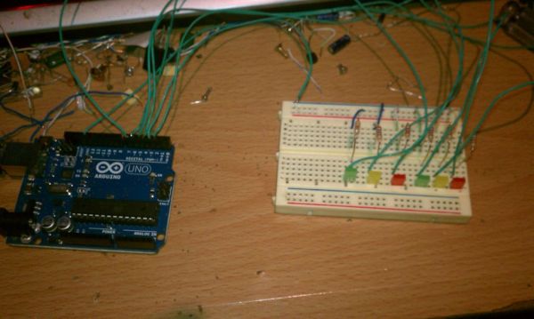
Step 2: Wiring
I used Pins 2 – 7 to make things easy. I don’t know if it hurts the Arduino to use both PWM and standard pins or not but, It works.
I wired up the grounds to the ground rail through the 270 OHM Resistors, it seems backwards to me, because I’m and electrician, to go to ground through a resistor but, I have seen this alot.
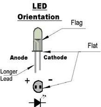
I took the 6 LED’s Anode lead and wired……
Side 1 Side 2
1 – Red to Pin 2 2 – Red to 5
1 – Yellow to 3 2 – Yellow to 6
1 – Green to 4 2 – Green to 7
Step 3: The Code
I hope I didn’t miss anything but if I did just comment.
The code I use seems simple, But I got confused so I had to get some help on figuring out what did what to who and how many.
There are some commented out sections that could come into play later.
1 – Breadboard
6 – 270 ohm resistors
For more detail: Another Arduino Traffic light
- Why did the author modify the code?
The author found existing web examples were too fast and needed realistic timing. - Which pins are used for the wiring?
Pins 2 through 7 are used to make things easy. - Can PWM and standard pins be used together?
The author states it works but does not know if it hurts the Arduino. - How are the LEDs connected to ground?
The grounds are wired to the ground rail through the 270 OHM Resistors. - What is the specific wiring for the first side of the LEDs?
Side 1 connects Red to Pin 2, Yellow to Pin 3, and Green to Pin 4. - What is the specific wiring for the second side of the LEDs?
Side 2 connects Red to Pin 5, Yellow to Pin 6, and Green to Pin 7. - Does the code contain future features?
Yes, there are commented out sections that could come into play later. - What background does the author have regarding the wiring method?
The author is an electrician who finds going to ground through a resistor backwards but has seen it done often.