Music is the most universal means of expression. Regardless cultural language or age the idea conveyed though music would not differ much. It is safe to say everyone loves music, one type or another. When one’s favourite piece is played there is a overwhelming desire to get involved and turn on one’s Air Guitar.
Not being familiar with any type of musical instrument myself. Moving my hand insanely in the air and imagining my virtual tone lines up perfectly along the music was the best I could do.
Why not put my engineering degree to use. Design something able to play music without any training, minimal music knowledge but still get that person highly involved.
Music box seems like a good start. The music is actually ‘played’ in real time, unlike mp3 music player which merely convert a string of data to time varying voltages. However the music storage method has to be changed, a drum with pins poking out does not allow much customization. If the music is stored on file we are back to the mp3 player, but if the music is on a piece of paper…..Now we are talking.
Hence the Electronic Music Box was conceived.
What you will need:
Step 1: Preliminary Design
How is the music stored on a piece of paper?
The simplest way is to divide a piece of paper, a certain width, into equal width columns and each represents a musical note of some sort. Kind of like musical notes on sheet music.
Notes are marked by pen and the duration of the note, or break, is controlled by the length of that mark.
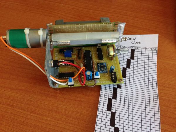
The paper with music notes should look something like the photo below.
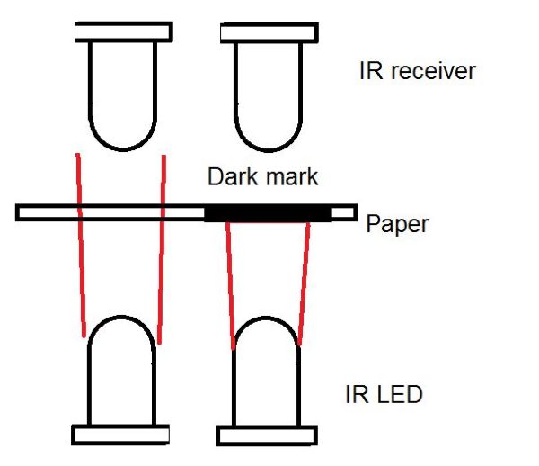
How does the unit read this paper?
A simple vision would be useful. Infrared, less likely to be distorted by our normal lighting is a great solution. Like visible light the dark mark on the sheet absorbs IR light while the blank passes most of IR through.
With this in mind the only thing we need to do to differentiate the two is a level comparison on the IR photodiodes.
How do we generate musical tone?
Since is fully electronics, the best tone generation method is that employed by mp3 players. Using a fast DAC or digital to analog converter to create the right voltage at a given moment, we can get a pretty smooth analog tone.
This method also allows any kind of waveform to be generated. It opens the possibility of polyphony.
Step 2: Circuit theory
The actual circuit design is not complex at all, only a lot of repetition. My design is split into two parts: Infrared sensor array and the main board.
The IR gate array is pretty simple. It’s just made up of a roll of 14 IR LEDs with a roll of 14 IR photodiodes facing each other. Why 14? Well it covers 2 Octaves and that is all I can manage to fit on that protoboard.
The IR sensors array provides 14 voltage levels according to the sheet and the circuit has to identify the marked notes. Thus we will need voltage comparators and that is where LM324 comes in. Strictly speaking LM324 is operational amplifier not voltage comparator but it can do the job just fine.
The choice of this IC is not based on its performance. Single supply, from 3V, having 4 amplifiers in one package is the main driving reason for the choice. Low power and low cost are also great bonus.
After the LM324 arrays convert the 14 IR gate signals to the simple HIGH or LOW digital signals. Then microcontroller takes over and does what it does best – calculation.
Based on the incoming signal, the microcontroller looks up on the waveform tables stored in its flash and grab the right voltage level appropriating to the moment in time. Since everything is software achieving polyphony is fairly easy. It is simply addition of all the voltage data.
The micro then passes this information to MCP4911 10bits DAC for the analog signal generation.
Step 3: Construction – IR gate arrays
This is a very simple part of the build but absolutely essential. The spacing between the IR LEDs must be kept constant. I am using a proto board with a standard pad spacing of 2.5mm, thus each LED is 5mm apart. A slot of 75mm is milled between the LEDs and photodiodes. This slot will allow the music sheet to pass through and be read. This board will be connected to the main board via header connectors. A row of 20 way right angle male header, not those straight ones in the photo, should be soldered and connected to the LEDs and photodiodes as shown in the circuit diagram. There is a reason I didn’t specify the value for the resistor R1 – R14. The value of these resistors will be our tuning points later on, at the moment use 100Ω for every one of them.
For more detail: Electronic Music Box Powered by Arduino (sort of)