Consider this the “Blinky LED” of the anduinoWiFi shield!
Things used in this project
Story
Motivation
Implementing an IoT prototype utilizing an Arduino that doesn’t natively support WiFi can be cumbersome. Sure there are some pretty good options for native support. The MKR1000 natively supports WiFi, but this ease comes at a price. The SAMD21 is essentially half as powerful as the SAM3X8E on the Due. Why not have the best of both worlds?
Give me the speed, storage, and excessive amount of I/O available on the Due with the same WiFi101 capabilities and ease of use as the MKR1000? Wouldn’t it also be nice to prevent your prototypes from looking like a labyrinth of wires and breadboards?
Enter AnduinoWiFi! Sure once you’ve connected the WiFi shield you’ve stolen away some I/O and shield real estate. Add on other critical IoT components like NFC, EEPROM, an LCD Display, and you usually start living on multiple breadboards. With our shield we’ve crammed it all onto one shield! (without compromising too many I/O pins) Let’s dig in and start testing out some of the built in features and components!
Getting Started
So you’ve just unboxed your shiny brand new anduinoWiFi shield, what’s next?
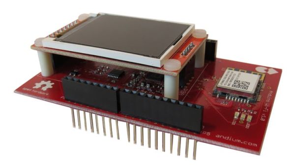
Whenever I buy something new I usually skip reading the user manual and immediately push all the buttons to see what they do. After stepping through this getting starting guide you’ll have essentially “pushed” all the buttons and explored the 4 major components found on the anduinoWiFi shield.
- WiFi connectivity (ATWINC1500)
- RFID/NFC card scanning (PN532)
- EEPROM storage (ST-M24256)
- LCD Display (160x128px ST7735)
Let’s kick things off with arguably the most important component of any IoT device, internet!
**For each component you’ll need to download and install libraries in the Arduino IDE. You can download utilizing the ‘Manage Libraries’ option within the IDE or by downloading from GitHub and transferring the files to your Arduino>>libraries directory. For the anduino libraries you’ll want to make sure you include the AnduinoPins Directory as well. This takes care of setting up the I/O for the shield behind the scenes If you haven’t done this before, check out Arduino’s step-by-step guide installing libraries.
Getting Connected With the ATWINC1500
The anduinoWiFi ships with the same WiFi module as the Arduino WiFi shield, the MKR1000, the Adafruit Feather M0 WiFi, just to name a few. This means that we can employ the same WiFi101 Arduino Library, community support, and documentation to get our prototypes working quickly. The ATWINC1500 is wired up just like the WiFi101 shield, so we can use any WiFi101 library example without any modification or adjustment for a different pinout.
To test out WiFi let’s attempt to connect to a web server utilizing https. Once you download and install the WiFi101 library navigate to File>>examples>>WiFi101>>WiFiSSLClient. Open the sketch and enter your WiFi SSID and Password here.
char ssid[] = "yourNetwork"; //  your network SSID (name)
char pass[] = "secretPassword";    // your network password (use for WPA, or use as key for WEP)
If you’d like to change the web server you connect to just modify this variable here:
char server[] = "store.andium.com";
Here’s where we connect to store.andium.com on port 443(HTTPS) and GET the home page:
 if (client.connect(server, 443)) {
   Serial.println("connected to server");
   // Make a HTTP request:
   client.println("GET / HTTP/1.1");
   client.println("Host: store.andium.com");
   client.println("Connection: close");
   client.println();
 }
}
So compile and run the code, open up your serial monitor and lets take a look! If all goes well you’ll see HTML returned to the terminal looking similar to what’s below!
<!--[if IE 9]> <html class="ie9 no-js" lang="en"> <![endif]-->
<!--[if (gt IE 9)|!(IE)]><!--> <html class="no-js" lang="en"> <!--<![endif]-->
<head>
<meta charset="utf-8">
<meta http-equiv="X-UA-Compatible" content="IE=edge,chrome=1">
<meta name="viewport" content="width=device-width,initial-scale=1">
<meta name="theme-color" content="#00cbf5">
<link rel="canonical" href="https://store.andium.com/">
<link rel="shortcut icon" href="//cdn.shopify.com/s/files/1/1789/9879/files/andiumfavicon_32x32.png?v=1487455314" type="image/png">
<title>
Andium Marketplace
– Andium Inc.
</title>
<meta name="description" content="Turn your Arduino into an andiumNode and start prototyping IoT solutions utilizing your favorite hardware!">That’s it! You’ve just tested out your anduinoWiFi’s ATWINC1500 and made a request to an HTTPS web server. Feel free to try any of the other WiFi101 example sketches, enter your WiFi credentials and give it a spin. When you’re ready to move on, lets test the NFC!
RFID Card Scanning with the PN532
The anduinoWiFi shield ships with NXP’s PN532 and a uFl connected RFID antenna used for scanning passive RFID tags at 13.56MHz. The anduinoNFC library also supports the NDEF format which we put to use in some other examples.
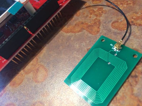 RFID antenna
To test out NFC on our shield we’re going to run the readRFIDTag example sketch and see if we can grab some information from the RFID Tag and display it in the terminal.
Navigate to File>>examples>>AnduinoNFC>>readRFIDTag and open the sketch. Even though we haven’t programmed anything on to the tag we can still read the UID and display some information about the tag.
Download the sketch, open the serial terminal, once prompted to ‘Scan an NFC tag’ approach the antenna with with a tag and wait for the output!
RFID Tag Reader
Found chip PN532
Firmware ver. 1.6
Scan an NFC tag
NFC Tag - NFC Forum Type 2
UID 04 96 A5 89 BA 5A 1F
NDEF Message 1 record, 18 bytes
 NDEF Record
   TNF 0x1 Well Known
   Type Length 0x1 1
   Payload Length 0xE 14
   Type 55  U
   Payload 04 67 6F 6F 2E 67 6C 2F 76 58 68 6C 72 69  .goo.gl/W4PiKW
   Record is 18 bytes
The Mifare Ultralight tag I’ve just scanned contains one record which stores a shortened URL. It’s unique ID is ’04 96 A5 89 BA 5A 1F’.
There are example sketches to read, write, format, erase, even a simple RFID Authentication example (keyCardAccess). To learn more about NFC check out some of our other tutorials utilizing the PN532. Now let’s test out the EEPROM.
EEPROM Read Byte Write Byte & LCD
EEPROM may be arguably the least exciting of the components on the anduino shield but none the less worth a look! You truly don’t realize how much you miss something until they take it away! Well, now we’ve brought the EEPROM back and it’s better than ever.
To spice things up a bit we’re going to test the LCD Display and the EEPROM at the same time. Make sure you have the AnduinoLCD and AnduinoNFC libraries loaded. To open the example sketch navigate to File>>examples>>AnduinoEEPROM>>wbyteRbyte. Flash the sketch and let’s check the LCD display for the output.
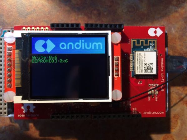
We just wrote ‘0x06’ hex to EEPROM address ‘0’.
 byte eebyte = 0x06;                 //what to write
 int eeaddress = 0;                  //where to write it
Let’s make a quick change to the sketch and store the character ‘A’ in address 2.
 byte eebyte = 'A';                 //what to write
int eeaddress = 2; //where to write it 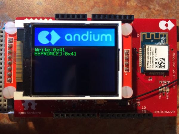
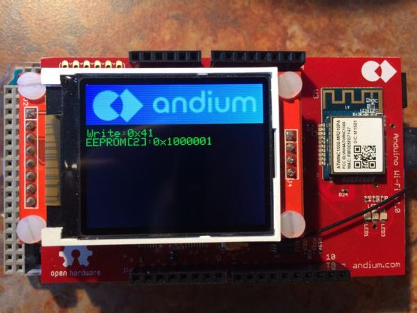 LCD.print(EEPROM.read(eeaddress), BIN);
This displays the HEX representation of the ASCII character ‘A’. You can use the same Serial.print() encodings for LCD.print (BIN, OCT, DEC, HEX, etc). Depending on what you’re storing in EEPROM it could be useful to interpret the data differently prior to displaying it.
Speaking of displaying things, did you notice the splash screen on start up? Within the setup code we called:
LCD.splashScreen();
Which in turn runs this code which you can find in the AnduinoLCD library source. Essential we draw a couple triangles to create our diamond, then gradually grow the circle by drawing multiple circles of increasing size, and lastly drop in the banner which contains our andium text and logo.
Curious about what other functions are available to you after including the AnduinoLCD library for interfacing with the LCD? Head on over to our Wiki pages!
//brief splashSccreen example to be used on startup draws Andium logo
void AnduinoLCD::splashScreen(void){
 //draw diamond of logo
 fillTriangle( 68,  80,  110,  40,  152,  80,  0x063E);
 fillTriangle( 68,  80,  110,  120,  152,  80,  0x063E);
 delay(100);
 //draw growing circle of logo encompasing diamond
   for(int i = 0; i<40; i+=2){
       fillCircle(60,  80,  i,  0x063F);
       delay(25);
   }
 //fill triangle again and draw circle outline to create overlay
 fillTriangle( 68,  80,  110,  40,  152,  80,  0x063E);
 fillTriangle( 68,  80,  110,  120,  152,  80,  0x063E);
 drawCircle( 60, 80, 39, 0x063F);
 delay(100);
 //drop in the banner
 showGimpImage(&andiumBanner);
 delay(500); //stare at it for half a second
}
Check out the project hub for more examples on how to create your own splash screen or to change the header banner to your own logo!
That’s it!
You’ve now essentially pushed all the buttons on the anduinoWiFi shield! Nice work! We’ve tested WiFi, NFC, EEPROM, and the LCD display.
If you haven’t already abandoned this guide to start messing around with NFC or WiFi and are still reading… vamos! Start building something awesome, and tell us all about it on twitter, facebook, or by posting a write-up in the project hub!
Code
Source : AnduinoWiFi Getting Started


