In the following tutorial, directions are given for creating a single node for the DoHas (Distributed Optical Harvard Architecture System). After constructing two of these nodes, a small distributed computer can be implemented which uses one node for sending instructions, mimicking input and the instruction set to manage it, and another node which will act as memory.

One unique feature about this system is that although it does separate the instruction and memory, it also has an important feature that is shared with the Von Neumann architecture, in that since both nodes are identical physically, they are both capable of fulfilling either role, depending on the state that either machine is in at the time of transmission.
This platform was designed by Marty Miller and William Tolley, two students at Berea College, and it should be pretty easily extensible. Have fun writing your own programs to be executed by our DoHas system.
Additionally, you may want a blank PCB board to create a permanent machine, as shown in the first photograph.
This project has been designed for individuals interest in creating small programming projects with the Arduino platform that may not necessarily have any background in creating circuits or following circuit diagrams. If this doesn’t apply to you, however, and you would rather simply follow a schematic of the project, one has been provided in addition to the step-by-step instructions.
Step 2: Preparing the Wires
The hookup wire should be cut into pieces as follows:
(9) 3 – 4 inch pieces with 1/2 inch exposed wire
(3) 6+ inch pieces with 1/2 inch exposed wire
Step 3: The Pins of the IR Receiver
The Left Pin is the pin that will be outputting data to the Arduino.
The Middle Pin is the ground.
The Right Pin is for receiving power.
Step 4: Wiring the IR Receiver
Instructions:
1.) Connect a 6 inch wire (to act as a global ground) from the GND port on the Arduino to the ground on the breadboard.
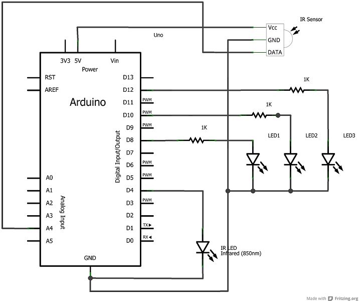
2.) Insert the IR Receiver onto the breadboard (location is not necessarily important).
3.) Connect a 6 inch wire from the 5V port on the Arduino to the Right Pin of the IR Receiver.
4.) Connect one of the short wires from the global ground area on the breadboard to the Middle Pin of the IR Receiver.
5.) Connect the last 6 inch wire from the A4 port on the Arduino to the Left Pin of the IR Receiver.
Acquiring Materials
For each node, you will need:
– Arduino
– Breadboard
– Infrared Emitter
– Infrared Receiver
– (3) 1,000 ohm resistor
– (3) LED
– solid core hookup wire
For more detail: A Study in Non-Standard Distributed Computer Architecture using Arduino