After some years of experimenting with Arduino, I decided that the time has come to share the knowledge I’ve acquired. So I here it goes, a guide to Arduino, with the bare basics for beginners and some more advanced explanations for people who are somewhat more familiar with electronics.
Every step will consist of a detailed explanation, then a summary, followed by a more advanced approach.
If you’re a complete beginner, I recommend reading the explanation first, and then the summary. There will (almost certainly) be some parts of the explanation you don’t understand. Don’t worry, it is absolutely normal, it will become clear after reading some other examples in the next steps, just don’t get discouraged!
I’ll provide some links to the Arduino reference page, Wikipedia, and some other interesting sources. If you want to know more about about a certain subject, these are great places to start. Again, if you don’t understand a word of those links, don’t worry, it is absolutely not necessary for this Instructable, and especially for beginners, they can be very confusing or even demotivating. If that’s the case, it might be better to skip them for now. But don’t give up!
Although a tutorial like this might be very helpful, you’ll learn mostly by experimenting yourself. Use this Instructable as a starting point, as a reference, but make your own projects, modify the given examples, try new things, search the internet, the possibilities are pretty much endless!
Step 1: What Is Arduino?

Well, first things first: What is Arduino?
Let’s take a look at the introduction from the Arduino website:
Arduino is an open-source prototyping platform based on easy-to-use hardware and software. Arduino boards are able to read inputs – light on a sensor, a finger on a button, or a Twitter message – and turn it into an output – activating a motor, turning on an LED, publishing something online. You can tell your board what to do by sending a set of instructions to the microcontroller on the board. To do so you use the Arduino programming language (based on Wiring), and the Arduino Software (IDE), based on Processing.
That actually says it all.
You can find the complete introduction here.
Maybe a little more information about the board:
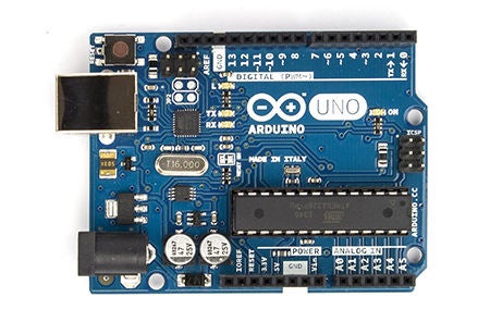
The Arduino Board itself is a blue circuit board, the size of a credit card (but they also have models in other sizes). It has two rows of connectors (the ‘headers’), a power connector and a USB connector. The brain of the board is an Atmel microcontroller. It’s like a really small, very low power ‘computer’. (It only has 32KB of storage, 2KB of RAM, and the 8-bit processor runs at only 16MHz.) For most applications, however, this is more than enough. The pins of the processor connect to the headers, and you can connect them to virtually anything you can imagine. You just need to write some lines of code to control them. The I/O pins (Input/Output) can be used as input pins, to connect buttons or knobs, temperature sensors, light sensors, or even keyboards and mouses, digital musical instruments … or they can be used as output pins, to connect LEDs, drive motors, control the lights in your home, connect to small displays or even connect to the Internet, so that it can check your mail, post tweets … Through the USB connection you can also use it to control your computer, or use your computer to control the Arduino.
As you can see, the sky’s pretty much the limit !
You can buy an Arduino from their website or from a local reseller for about $22 (€20).
To get an idea of what you can do with an Arduino board, check out the Arduino blog or the Arduino channel here on Instructables.
Step 2: Before You Begin…
How not to fry your Arduino
Before you begin plugging things into your new Arduino, it may be good to know what can damage the board.
- Drawing more than 40mA from an output pin.
An Arduino can only supply 40mA per output pin, so you cannot drive a motor or a speaker directly, for example, and you cannot connect an LED directly (without a resistor). In the course of this Instructable, I’ll explain what you should do instead.
Shorting an output in to the +5v, +3.3v or the ground pins, will also kill your board: If an output pin is at 5v for example, and you connect it to the ground, it draws an enormous amount of current, and kills your Arduino almost instantly.
The pins go through the circuit board, so make sure you don’t place the Arduino on a conductive (metal) surface, because it will short out the pins. - Drawing more than 200mA from all output pins together.
The ATmega chip on your Arduino can only supply 200mA in total, so driving more than 10 LEDs @ 20mA each, for example, will eventually damage your board. - Supplying more than 5v (3.3v) to an input pin.
Supplying more than the operating voltage of the Arduino on any pin is very dangerous. Some Arduinos that run at 3.3v have 5v tolerant pins, but that’s about it. This also holds true for other devices, like sensors or wireless chips: always check the voltages: if you connect the output of a 5V Arduino to a 3.3V chip, you might kill it. - Supplying more than 5v to the 5v pin.
The 5v of the Arduino board goes directly to the ATmega chip, that is rated for an absolute maximum of 6v. - Supplying more than 12v to the Vin pin.
There’s an onboard 5v voltage regulator on the board, that will overheat and die if you feed it with more than 12v. - Drawing more than 500mA from the 5v pin (when running off an external power supply.
The onboard 5v voltage regulator can only supply 500mA of current. The 5vUSB has a polyfuse to limit the current to 500mA. - Drawing more than 50mA from the 3.3v pin.
The onboard 3.3v voltage regulator can only supply 50mA of current. This means that you can not connect power hungry 3.3v devices like an ESP8266 or nRF24L01 directly to the Arduino: you need an external 3.3v voltage regulator. - Reversing the polarity of the power supply.
If you swap the 5v or Vin pin with the GND pin, you’ll kill the board almost instantly.
The barrel jack has a diode to protect against reverse polarity. - Connecting a load to the Vin pin while using USB power.
If you connect a load to the Vin pin while the 5v to the Arduino comes from the USB connection, current will flow backwards through the voltage regulator, damaging it. - Static electricity
Although most chips have clamping diodes as protection against ESDs (electrostatic discharges), it may be wise to us an anti-static wrist strap, or to remove the carpet under your desk.
Step 3: Software

Arduino IDE
For programming our Arduino, we’ll need the Arduino IDE (integrated development environment).
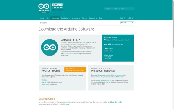
It can be downloaded from the site.
Windows:
- Go to the site, go to Download, and select the Windows installer.
- Consider donating some money, if you want to support the project, and click download.
- Click the downloaded file to run it.
- Grant administrator permission.
- Agree to the License Agreement.
- Select the appropriate boxes, you’ll need the Arduino Software and the USB driver, the other three are optional.
- Accept the default installation folder, or pick another one. Then click install.
- When you’re prompted whether or not you want to install the Arduino USB Driver (device software), click install.
- Wait for the installer to complete, and launch the Arduino IDE.
(A complete installation guide can be found on the Arduino website as well.)
Ubuntu:
- Go to the site, go to Download, and select the right Linux version.
- Consider donating some money, if you want to support the project, and click download.
- Open a terminal window (CTRL+ALT+T), and run these commands, changing the filename appropriately
- cd Downloads
- tar xf arduino-1.6.11-linux64.tar.xz
- sudo mv arduino-1.6.11/ /opt/arduino-1.6.11/
- /opt/arduino-1.6.11/install.sh
- sudo usermod -a -G dialout $USER
This goes to the Downloads folder, unzips the downloaded file, moves it to the /opt/ folder, and runs the install script. This install script will create a desktop file, and a MIME type to associate .ino files with the Arduino IDE. Finally, you have to add (-a = append) your user to the ‘dialout’ group (-G), in order to have access to the serial ports. ($USER is a system variable for the current user) If you open the Arduino IDE now, you’ll see that the Tools > Port option is grayed out. When your user is added to the dialout group, log out, and sign back in. Your Arduino’s serial port should now be available in the IDE.
Arduino IDE + Teensyduino
If you have a Teensy board, you’ll need the Teensyduino add-on for the Arduino IDE. The installation is very simple, and a very good install guide can be found on the Teensy site.
Teensyduino currently doesn’t support the latest versions (1.6.10 & 1.6.11 @07-09-2016) of the Arduino IDE yet, so you’ll have to download a previous version. (1.6.9)
If you’re running Linux, you may come across this error while installing Arduino:
bash: /opt/arduino-1.6.6/install.sh: Permission denied
If this is the case, try running
sudo chmod +x /opt/arduino-1.6.6/install.sh
This adds (+) the permission to be executed (x). Then try running /opt/arduino-1.6.6/install.sh again.
Example sketches
I added a .ZIP file with all the example sketches I’ll be using throughout this Instructable, download and unzip it so you can follow along, or even modify them to your own needs if you want to.
Step 4: Hardware & Electronics

Before we begin, I’ll explain some of the basic electronic components. If you only just started with electronics, this is for you!
Sometimes I’ll use some physics to explain how a certain component works, this is just a side note, it doesn’t really matter if you don’t understand this yet. It’ll take some time to get used to.
If you want to go further into electronics, however, you’ll find out that electronics is just applied physics.
I also provided some links to videos on YouTube that helped me understand the basic principles of the different components.
Basic physics
Electricity is the flow of electric charge carriers: electrons (in most cases).
Electrons are the negatively charged particles that whirl around the positively charged nucleus (core, plural: nuclei) of an atom.
Electrons can move easily through metals, like copper, silver, gold … We call these materials conductors.
These materials have freely moving electrons.
Materials like plastic, wood, glass, air … don’t conduct electricity very well. They are called insulators.
They don’t have moving electrons or other charge carriers.
A piece of material that has more negative charges (electrons) than positive ones (nuclei with positive protons), is negatively charged.
A piece of material that has less negative charges than positive ones, is positively charged.
(Note that only the electrons can move, the positive nuclei are stuck in a grid.)
Just like magnets, opposite charges attract each other: when you have one piece of material that has more electrons, and one piece that has less electrons, the electrons in the negative piece will be attracted to the positive piece. If there’s a conductor in between these pieces, these electrons will ‘flow’ to the positive part: This is electric current.
Current expresses the amount of charges that flow through a conductor per unit of time. Its unit is Amps (Ampère), and is defined as C/s, where C is Coulomb (charge) and s is seconds (time). Its symbol is I.
A battery has a negative side that has more electrons, and a positive side that has fewer electrons. Like I said earlier, the electrons will try to reach the positive side, but they cannot go through the internal circuit of the battery itself. This gives the electrons potential energy. This is the energy that is released as light and heat in a bulb, as motion (kinetic energy) in a motor … The difference in potential energy of a charge at the positive and a charge at the negative side, is called the voltage. The unit is Volts, and is defined as J/C, where J is Joule (SI-unit of energy) and C is Coulomb (SI-unit of charge). This expresses how much energy a certain charge (read: certain amount of electrons) releases.
The symbol for Volts is V or U (from the German word ‘Unterschied’, difference, and refers to the potential difference).
Power is the amount of energy that is released per unit of time. The SI unit is Watts, and is defined as J/s where J is Joules, and s is seconds. If you multiply current by voltage (C/s ∙ J/C) the C cancels out, so you get J/s. This means that voltage multiplied by current gives you the wattage.
In most schematics, the conventional current flow is used: arrows are drawn from the positive side to the negative side. In practice, however, only electrons can move, so the actual direction of the current flow is from the negative side to the positive side.
Resistors
Resistors are components with – as the name implies – an electrical resistance, in other words, they limit the flow of electrons, so they are often used to limit the current.
The SI unit of resistance is Ohms, often written as the Greek letter omega (Ω). They are often used with the unit prefixes kilo (k) and mega (M). E.g. 1.2MΩ = 1M2Ω = 1,200kΩ = 1,200,000Ω = 1,200,000E = 1,200,000R. (note that writing a digit after the unit prefix is the same as writing it after the decimal point. Also, in some schematics, E or R are used instead of Ω).
The value of a resistor is indicated by 4 (or 5) colored bands, using the resistor color code:
The first 2 (or 3) bands are the 2 (or 3) first digits of the value, and the 3rd (or 4th) band is the power of ten that comes after those 2 (or 3) digits. This is also called the multiplier, and is just the number of zeros you have to add. The last band is the tolerance, and is mostly silver or gold.
E.g. red red red gold = 22 x 100Ω = 2,200Ω = 22 x 10² Ω = 2k2Ω = 2.2kΩ, with a tolerance of 5%; green blue black brown red = 560 x 10Ω = 5,600Ω = 5k6Ω = 5.6kΩ, with a tolerance of 2%.
The relationship between resistance, voltage and current can be calculated using Ohm’s Law.
I = V/R
where I is the current in Amps, V the voltage in Volts, and R the resistance in Ohms.
This is a very, if not the most important formula in electronics, so try to remember it!
Capacitors
A capacitor is an electrical component that can store electrical charge (in the form of electrons).
Although they are fundamentally different, in some ways, it behaves like a small rechargeable battery.
When a voltage is applied to a capacitor, the potential difference (a difference in number of electrons → the side with more electrons has a negative charge, compared to the other side) These electrons can flow out of the capacitor again, when the voltage is no longer applied, just like a battery.
Capacitors are used in filters, for example to filter out the 50/60Hz noise from your power supply, or to filter high frequencies out of your music when you turn on the low-pass filter, or turn the bass and treble knobs on your amplifier. In these cases, the capacitor charges and discharges really quickly.
Another use for the capacitor, is filtering out DC voltage.
The SI unit of capacitance is Farad, or F. This is a very large unit, and most often, you’ll see prefixes like pico (p), nano (n) or micro (µ).
On some smaller capacitors, the capacitance is written using a three-digit number. The first two digits are the first two digits of the value, and the third digit is the power of ten to multiply it with. The unit of the value you get is picofarad.
E.g. 104 = 10 x 10⁴ = 100,000 pF = 100 nF = 0.1 µF (= 0.0000001 F)
Larger capacitors, the electrolytic type, (mostly the cylindrical ones) have a polarity, marked by a grey line. If you connect them the wrong way around, they can explode, be careful!
Read more: A Beginner’s Guide to Arduino
