
Summary of Boost Converter Circuit in Proteus Using uc1845
Boost Converter Circuit in Proteus Using UC1845 — Summary: This article explains a boost converter circuit simulated in Proteus using the UC1845 current-mode PWM controller. It lists input (10–15 V) and output (20–50 V) ranges, component values, MOSFET choice, diode, inductor, capacitors, resistors, and notes common applications and an advantage of providing higher output voltage.
Parts used in the Boost Converter Circuit in Proteus Using uc1845:
- IC UC1845 (Current Mode PWM Controller)
- Battery (input voltage 10 to 15 V)
- C1 4.7 nF capacitor
- C2 100 nF capacitor
- C3 270 pF capacitor
- C4 1 nF capacitor
- C5 47 uF capacitor
- C6 100 nF capacitor
- R1 30 kΩ resistor
- R2 100 Ω resistor
- R3 500 Ω resistor
- R4 0.5 Ω resistor
- R5 9 kΩ resistor
- R6 1 kΩ resistor
- D5 1N4001 diode
- L1 100 µH inductor coil
- FET IRF840 or alternative IRF540 N-channel power MOSFET
This article is all about boost converter circuit, what is boost converter circuit and how it is useful in boost converter circuit .and its ic number. Keep reading if you want to know about boost converter circuit in proteus using uc1845
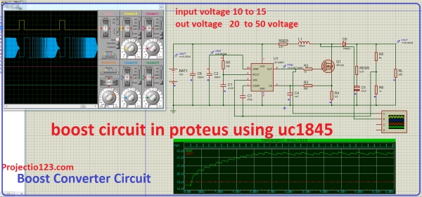
Boost Converter Circuit in Proteus Using uc1845
input voltage 10 to 15
out voltage 20 to 50 voltage
Components Required
ic =uc1845
batt1 = input voltage
c1 4.7nf
c2 100nf capacitor
c3 270p
c4 1nf
c5 47uf capacitor
c6 100nf
r1 30k Resistor
r2 100 oham
r3 500 ohm
r4 0.5 ohm
r5 9k
r6 1k
d5 1n4001 diode
l1 100uh inductor coil
fet irf 840 or any other IRF540 N-Channel Power MOSFET
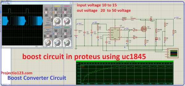
boost converter ic
UC1845 is a Current Mode PWM Controller Designed by texas instruments.it is used for boost converter
boost converter applications
The applications of boost converter is below
- boost converter is used in Battery power mangement
- boost converter is used for Power amplifier circuits
- boost converter is used in DC motor drives
- boost converter is used for dc to dc step up voltage converter circuit
Boost Converter Circuit Advantages
boost converter circuit Gives the high ouput voltage
Source: Boost Converter Circuit in Proteus Using uc1845
- What is the IC number used in the boost converter circuit?
The IC used is UC1845. - What input voltage range is used in the described boost converter?
The input voltage range is 10 to 15 V. - What output voltage range does the boost converter provide?
The output voltage range is 20 to 50 V. - Which MOSFET is suggested for the boost converter?
IRF840 is suggested, or any other IRF540 N-Channel power MOSFET. - What diode is used in the circuit?
The diode used is 1N4001. - What value inductor is specified for the boost converter?
The inductor specified is 100 µH. - What are some applications of the boost converter mentioned?
Applications include battery power management, power amplifier circuits, DC motor drives, and DC to DC step-up voltage conversion. - What is one advantage of the boost converter circuit noted in the article?
An advantage is that the boost converter gives a high output voltage.
