Summary of Basic IC Tester Using Arduino NANO
This project is a Basic IC Tester using an Arduino Nano (or Uno) on a two-layer PCB that tests logic ICs (specifically 7408 and 7432) by applying predefined op-codes and indicating results with LEDs: green for good, red for bad. It includes circuit design, Proteus simulation, and Arduino code uploaded via the Arduino IDE. The design can be expanded to test up to eight ICs depending on pin availability.
Parts used in the Basic IC Tester Using Arduino NANO:
- PCB (Dotted Board)
- 9V Battery with connector
- T-Block (Header block)
- 7805 Voltage Regulator
- ZIF Socket (latched IC base)
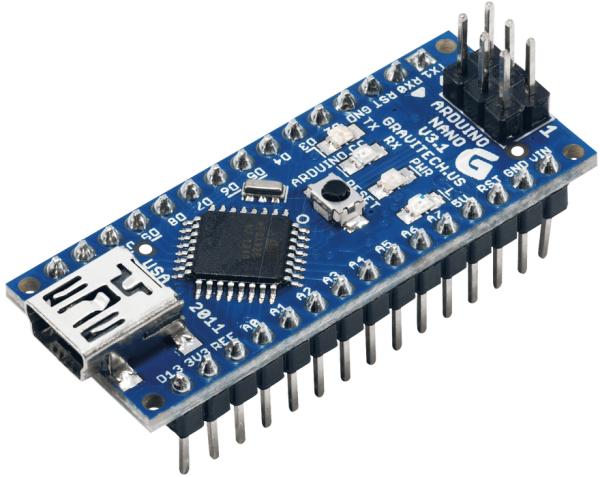
- Arduino NANO (or Arduino UNO)
- Female jumper sockets
- LEDs: Green LED - 1, Red LED - 1, Blue LED - 4
- Resistors: 150 Ohm resistors (for LEDs)
- Connecting wires
- Soldering gun and soldering materials
- Push button (Reset button)
- ON/OFF Button
1. Components required for this project.
2. Procedure to do this project.
3. Coding of Arduino Nano with verification.
4. Circuit diagrams.
5. Simulations and application list.
So lets begin…..!
Step 1: What This Project Dose ?
Basic Information and working of this project is,
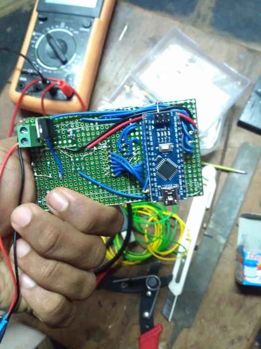
Basically this is the easiest project with Arduino Nano but more of thinking in the code. This project involved with circuit design and coding. This is done by 2 layer PCB and Arduino Nano, which test the basic IC’s like gates.
This project is made to test only two IC’s ( 7408 and 7432 ), But we can increase this design to 8 IC’s based on the type of IC and compatibility with Arduino Nano pins.
This project Does :
Testing the IC placed with per-defined Op-Code and resulting with LED’s. If Green LED glows then the IC is good, If Red LED glows then the IC is not good. Indicating these two results we can test the given IC.
So let’s begin …!
Step 2: Components Required :
All required Components are :
1. PCB (Dotted Board ).
2. 9V Battery with connector.
3. T-Block ( Header block ).
4. 7805 Regulator.
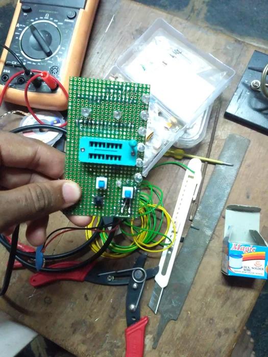
5. ZIF Socket ( latched IC Base ).
6. Arduino NANO ( Arduino UNO )
7. Female jumper sockets.
8. LED’s and Resistors. ==> Green LED – 1, Red LED – 1, Blue LED – 4 and 150Ohms Resistors
9. Connecting wires.
10. Soldering gun and other materials
11. Push Buttons ( Reset button )
12. ON/OFF Button.
That’s it ….! So let see how to do it !.
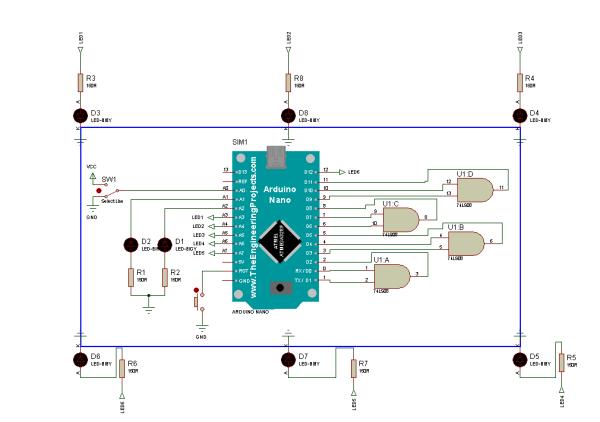
Step 3: Circuit Diagram and Connections.
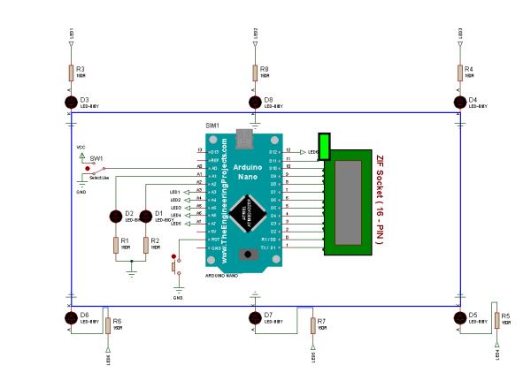
Circuit Diagram is shown in the image, connect the components according to it.
While connecting the Switches take care of Ground connection.
Step 4: Simulation Using Emulator
This is Proteus V7 Simulator which act as Emulator for Arduino Nano. By using this i have done the testing and optimization of my code. Please check my posts to know more about Proteus V7.
Generic Power Supply Board : https://www.instructables.com/id/Generic-Power-Su…
Channel 12V DC Relay Board : https://www.instructables.com/id/3-Channer-12V-DC…
Arduino Uno R3 Board : https://www.instructables.com/id/Arduino-Uno-R3-B…
BLC using Arduino Emulator : https://www.instructables.com/id/BLC-Using-Arduin…
Hope you get the best from these.
Step 5: Arduino Coding and Optimization.
Arduino IDE is open source software, Download it and install.
This is source code which I written for this project, If you have any doubts or suggestions I’m always happy to listen you !
Now you all set with design and implementation, So let us test how it works ?
Source: Basic IC Tester Using Arduino NANO
- What does this project do?
It tests logic ICs (7408 and 7432) by applying predefined op-codes and shows results with LEDs: green for good, red for bad. - Which ICs are tested by this design?
It is made to test two ICs: 7408 and 7432, with potential to expand to eight ICs. - What microcontroller is used in the project?
Arduino NANO is used, and Arduino UNO can be used alternatively. - What power supply is required?
A 9V battery with connector is used along with a 7805 regulator to provide 5V. - How are test results indicated?
Results are indicated by LEDs: green LED for good IC, red LED for bad IC, plus four blue LEDs used in the circuit. - Is there a simulation available for the project?
The author used Proteus V7 simulator to emulate Arduino Nano and test the code. - Where is the Arduino code developed and uploaded?
Code is written and uploaded using the Arduino IDE. - What socket is used to place ICs for testing?
A ZIF socket (latched IC base) is used to place the IC under test. - Are circuit diagrams provided?
The article states a circuit diagram is shown and components should be connected accordingly, with attention to switch ground connections. - Can the design be expanded to test more ICs?
Yes, it can be increased to test up to eight ICs depending on IC type and Arduino Nano pin compatibility.