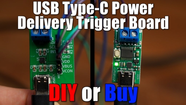
In this video we will have a closer look at a USB Type-C Power Delivery Trigger board. Such boards are used to output 5V, 9V, 12V, 15V or even 20V from a Power Delivery compatible power source. So I will be showing you how such a commercial board works and I will try to create my own DIY version of it in order to see whether it makes sense to DIY such a board or whether we should stick to the commercial solution instead. Let’s get started!
Step 1: Watch the Video!
Make sure to watch the video. It will give you all the information you need to create your own USB Type-C PD Trigger board. During the next steps though I will give you some additional information.
Step 2: Order Your Components!
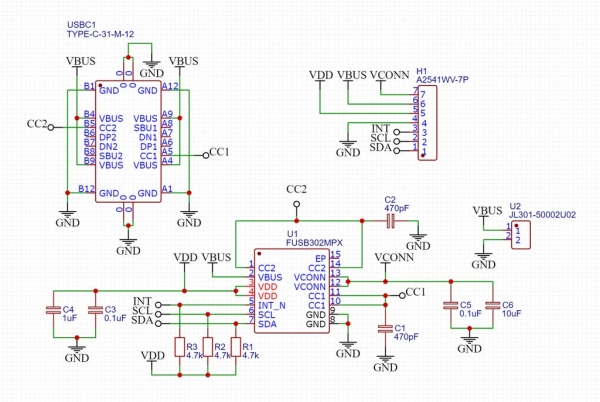
Here you can find the schematic for the project which shows you what components you will need for the PCB. You can order them here: https://lcsc.com/
Step 3: Get Your PCBs!
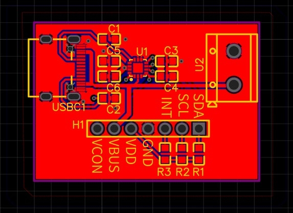
Here you can find the Gerber files for my PCB. Feel free to upload and order them here: https://jlcpcb.com/
Step 4: Do the Wiring and Upload the Code!
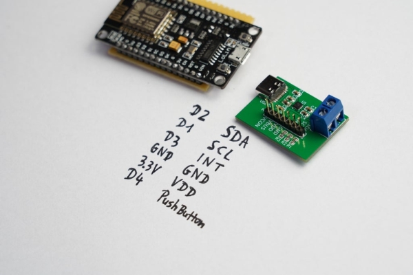
Here you can find the wiring diagram for the ESP8266 and the FUSB302 board along with the code provided by Reclaimer Labs.
Step 5: Success!
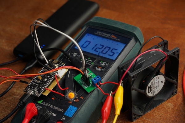
You did it! You just created your own USB Type-C PD Trigger board!
Feel free to check out my YouTube channel for more awesome projects:
http://www.youtube.com/user/greatscottlab
You can also follow me on Facebook and Twitter for news about upcoming projects and behind the scenes information:
https://www.facebook.com/greatscottlab
Source: DIY USB Type-C Power Delivery Trigger Board
