
Summary of Drifter – Arduino controlled RC car
The Drifter project transforms a cheap RC toy car into an Arduino-controlled vehicle. The builder integrated an Arduino Pro Mini onto the rear axle, intercepting signals between the RC receiver and motor drivers to enable smooth PWM control while retaining the original remote for mode selection. Future plans involve adding autonomous navigation using a 3.3V ultrasonic sensor to replace the current 5V incompatible HC-SR04.
Parts used in Drifter:
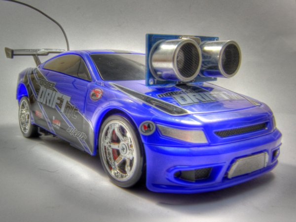
- Fast lane Monster Drift RC toy car
- Arduino Pro Mini
- RC receiver IC
- 2 H-Bridges (drive and steering motor)
- Voltage regulator (3.3V)
- PWM capable pins 5, 6, 9, 10
- Remote control
- HC-SR04 ultrasonic sensor (current prototype, requires replacement)
- SRF01 or Maxbotix ultrasonic sensor (planned upgrade)
Drifter is based on a cheap RC toy car I found at Toys’r’us, named ‘Fast lane Monster Drift’. I think it’s the same model Frits has been used in an episode of TLIHR. It doesn’t work well, you get what you pay for. But it is a good hacking platform. There is no much space left for additional electronics, but a Arduino Pro Mini fits very well on the rear axle.
The onboard electronic is as usual very primitive. A PCB with a RC receiver IC, 2 H-Bridges for drive and steering motor, and a voltage regulator (3,3V). Lucky me I found the control signals going from the RC receiver to the motor drivers and an easy way to cut these connectors and put the Arduino between. That way I can use the existing remote control. 4 Inputs and 4 outputs were needed (forward, backward, left and right). As outputs the PWM capable pins 5,6,9,10 has been used to give the possibility of smooth movements, instead full speed drive and steering from the original hardware.
The Remote control is used as a mode selector. On power up the Arduino reads the remote and executes the selected mode of operation.
Further development:

To make the car autonomous it needs a ultrasonic sensor. Unfortunately I only have a HC-SR04 ultrasonic sensor ready, witch is a 5V device. The existing electronics and the Arduino are 3.3V powered. So the HC-SR04 needs to be replaced with a SRF01 or Maxbotix sensor. Both work with 3.3V.
For more detail: Drifter – Arduino controlled RC car
-
What is the base platform for the Drifter project?
The project is based on a cheap RC toy car named Fast lane Monster Drift found at Toys'r'us. -
How does the Arduino fit into the existing electronics?
An Arduino Pro Mini fits very well on the rear axle where there is limited space. -
How are the control signals managed between the receiver and motors?
The author cuts the connectors from the RC receiver to the motor drivers and places the Arduino in between. -
Which Arduino pins are used for output to ensure smooth movement?
Pins 5, 6, 9, and 10 with PWM capability are used instead of full speed drive. -
What is the function of the remote control in this setup?
The remote control acts as a mode selector that the Arduino reads upon power up. -
Why must the HC-SR04 sensor be replaced for future development?
The HC-SR04 is a 5V device while the existing electronics and Arduino are powered by 3.3V. -
Which sensors are recommended for the autonomous upgrade?
The SRF01 or Maxbotix sensors are recommended because they work with 3.3V.
