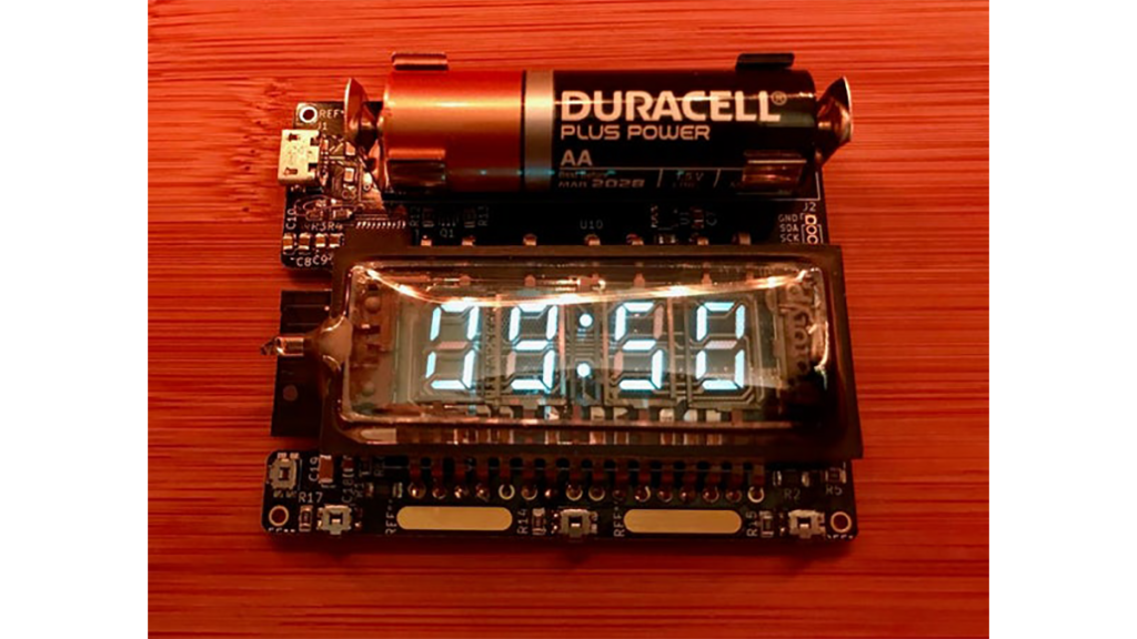
Summary of Vacuum Fluorescent Display Watch
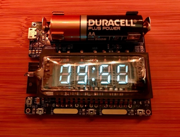
This article details the creation of a wristwatch featuring a Soviet-era IVL2-7/5 Vacuum Fluorescent Display (VFD). The project was inspired by a 2014 Hackaday build and involves driving the VFD using an ESP32 microcontroller. Key challenges included generating the required 24V for the anode and 2.4V AC for the filament from a single AA battery using boost converters and an H-bridge. The design utilizes KiCad for PCB layout, JLCPCB for manufacturing, and Arduino with PlatformIO for software development, resulting in a compact, Wi-Fi enabled timepiece.
Parts used in the VFD Watch:
- IVL2-7/5 VFD
- ESP32 (Wroom-32 module)
- FTDI USB-Serial converter
- MP3120 boost converter
- MCP1663 boost converter
- TBD63783A high-side switching ICs
- MCP23017 16-bit I2C expander
- AA alkaline battery
- KiCad5 software
- JLCPCB PCB service
That whole project started a while back with an hackaday article from 2014 in which [Johngineer] build the ‘ChronodeVFD’, a wristwatch made from an old soviet vacuum fluorescent display. It kind of triggered the ‘shut up and take my money’ reflex in me, but as it wasn’t for sale and didn’t have any design details available I quickly had to scrap that.
Fast forward a bit, during a late night eBay shopping spree (as one usually does…), I stumbled upon a listing from an Ukrainian guy who sold an IVL2-7/5 VFD – the exact same model used for the ChronodeVFD. After a bit of back and forth with the seller I ended up with a box of these babies neatly wrapped in what seems like Russian newspaper – nice!
However, I now realised that I had no clue how to drive these things or even how they worked, so some googling was in order.
Step 1: What the Hell Is an VFD and How Does It Work?
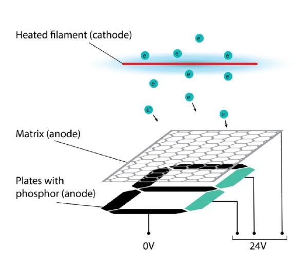
Vacuum fluorescent displays work kind of like a CRTs where accelerated electrons are bombarded on a layer of phosphor which then emits this typical blue-greenish light. VFDs are driven with much lower voltages compared to CRTs which is why they are often found in small consumer equipment predating the LCD-era.
In order to create free electrons a filament is heated within the VFD, the cathode (at negative, or in our case ground potential). This creates an electron cloud around the filament, which will be accelerated towards any positively charged surface, here the plates of the anode. This on its own works already, but would require a separate pin for each segment on the display to drive it. To reduce the number of inputs, most VFDs are multiplexed with a matrix above each substructure like a 7-segment. Only when the plate and its matrix are at a positive voltage electrons will hit the phosphor surface.
The IVL2-7/5 is controlled with an anode voltage of around 24V for the matrix and plates. The filament is heated with 2.4V AC. The AC is needed to even out the voltage difference between the filament and the anode. If DC is used, the side closer to ground will be at a higher voltage difference (0-24V vs 2.4-24V) and may be brighter than the other side. In practice the difference is hardly noticeable.
Step 2: Testing
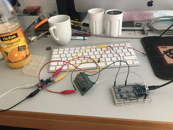
Initially I didn’t have a datasheet for the display, so I had to resort to trial-and-error testing. The filament pins can easily be found by measuring the resistance between them as it should be in the order of tens of Ohms. All the other pins are either a short or open circuit.
In the end I found the original datasheet, so this wasn’t really necessary…
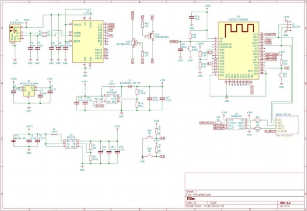
Step 3: Circuit Design & PCB Layout
The watch was designed with the following specifications in mind:
- Run (briefly) from a AA alkaline battery
- Compact size
- Wifi & Bluetooth
- Easily programmable
The brain of the watch is an ESP32 (Wroom-32 module) as it can be programmed via Arduino and has build in Wifi/Bluetooth and a very low power sleep mode. To interface with the ESP32 a FTDI USB-Serial converter was used.
The most challenging part of this project was to get the different power supply correctly designed. The VFD needs 24V for its anode and ideally 2.4V AC for the filament. The ESP32 also need its share of 3.3V at more than 240mA when heavily using wireless communications. All that has to be squeezed out of a 1.5V AA alkaline cell.
Early on the 2.4V AC was replaced by just using 3.3V on the filament and modulating the output with an H-bridge to not burn up the filament. It actually can survive 3.3V for a bit, but quickly turns into a light bulb…
The 3.3V is generated using a MP3120 boost converter, that is specifically designed to work with single cell alkaline batteries. It can theoretically go down to 0.8V, but in practice only at very low currents. But it has a built in linear regulator, that allows the use of batteries with higher than 3.3V voltage like 14500 lithium cells.
24V for the VFD comes also from a boost converter MCP1663. This one is less efficient due to the high step-up from 3.3V to 24V. The display also works at lower voltages down to 16V, but loses much of its brightness.
To switch the 24V on the display anodes 2 high-side switching ICs TBD63783A with a 16 bit I2C expander (MCP23017) are used. This can also be done with discrete PNP & NPN transistors, but due to limited board area I opted for the more integrated solution.
The whole design and layout was done with KiCad5.
Step 4: Assembly and Some Troubleshooting
The PCB were ordered from JLCPCB with black solder mask and gold plating (because why not…). The assembly was done by hand.
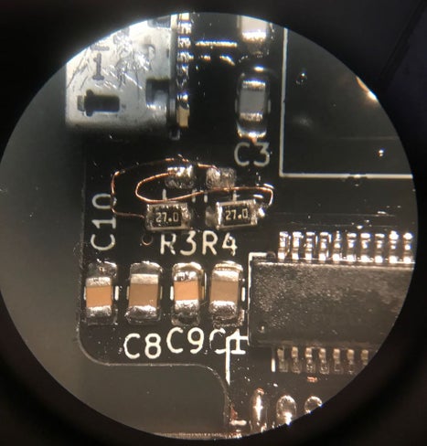
Initially the USB-Serial converter didn’t work, but after some troubleshooting this was due to mixed up data lines on the USB connector, that were fixed with some bodge wires as seen in the picture above.
Step 5: Code
The software was written with Arduino using PlatformIO.
The full source code and design files can be found on GitHub:
https://github.com/Pakue95/VFD_Watch
Thanks for reading!
Source: Vacuum Fluorescent Display Watch
- How does a Vacuum Fluorescent Display work?
VFDs function like CRTs where accelerated electrons bombard a phosphor layer to emit blue-green light, driven by lower voltages than CRTs. - What voltage is required for the VFD anode and filament?
The display requires around 24V for the matrix and plates, and 2.4V AC for the filament. - Why is AC needed for the filament instead of DC?
AC is used to even out the voltage difference between the filament and the anode, preventing uneven brightness. - How is the 24V generated from a single AA battery?
An MCP1663 boost converter steps up the voltage from 3.3V to 24V for the display anodes. - Which microcontroller was chosen for the watch brain?
An ESP32 Wroom-32 module was selected for its programmability via Arduino, built-in Wi-Fi and Bluetooth, and low power sleep mode. - What software tools were used for circuit design and coding?
The PCB layout was done with KiCad5, while the software was written using Arduino with PlatformIO. - How are the 24V lines switched on the display?
Two TBD63783A high-side switching ICs paired with an MCP23017 I2C expander control the anodes. - What happened during the initial USB-Serial testing?
The converter initially failed due to mixed-up data lines on the USB connector, which were fixed with bodge wires.