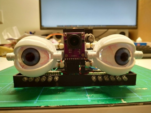
This Arduino project uses an Optical Flow Sensor (ADNS3080) to capture movement.
Then translate the data to move servo’s making it look as eyes are following moving object.
This is not an easy build.
It requires 3d printing, soldering, some general technical understanding and problem solving as this guide cannot be 100% perfect.
I will do my best to make this as comprehensive and illustrative as I can.
Feel free to ask questions and leave your comments.
I want to thank the “maker” community and all the people who share there projects.
Now Lest make some cool motion follow eye animatronics.
Step 1: Overview
Step 2: Part List
1x Arduino Nano 3.0 ATmega328P Controlador
6x SG90 9g Mini Micro Servo
1x Optical Flow Sensor APM2.5 ADNS 3080
1x 50*70 PCB
2x Single Row Female Pin Headers
2x Single Row Male Pin Headers
x2 5 pin Dupont wire cable connectors 2.54 mm Jumper Header Housing Female
x2 2 pin Dupont wire cable connectors 2.54 mm Jumper Header Housing Female
1x Mini 3 Pin Dashboard On Off Position Rocker Switch Illuminated
1x Dc Power Jack Socket Connector (Diameter Dependent on you power source)
4x 2MM Green/Yellow/Blue/Red/ LED Light Diode
12x IR LED 850nm Infrared 5mm Diodes
1x XL4005 DSN5000 Beyond LM2596 DC-DC
16x 220R resistor
1x LM8UU Linear Bushing 8mm linear ball bearing
1x 100mm Smooth Shaft Rod Chromed stainless steel Diameter 8mm
8x M2 Stainless Steel Flat Head Countersunk Phillips Machine Screws
4x M3 Screws Hex Socket Flat Head
11x Plastic M3 Ball Buckle Tie Rod End Positioning Ball Buckle link Push/Pull Rod
6x M2 L300mm Link Stainless Steel Connecting Rod with Dual End Thread for Servos
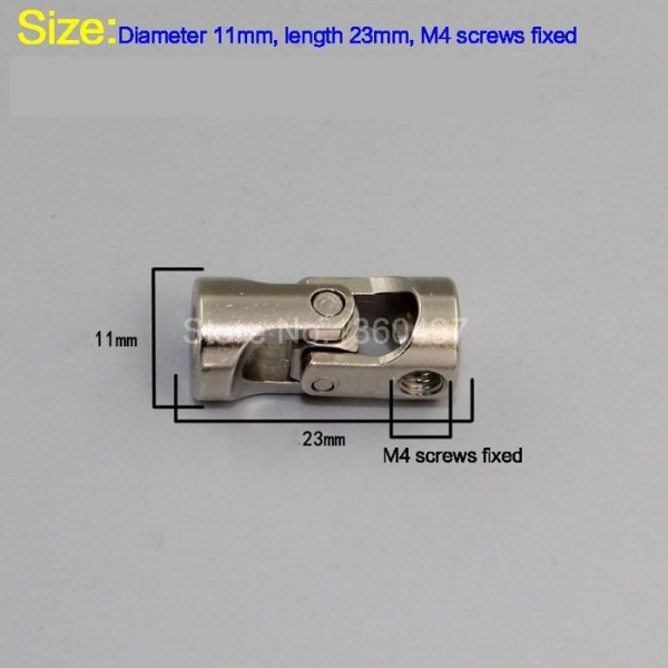
2x 11/23 M4 screw Metal Cardan Joint Gimbal Couplings Universal Joint (see pic)
3x 3D Printer Filament White\Black\Transparent Blue
Step 3: Tools
- 3d printer
- Soldering iron
- Hex key set
- Small screwdriver (M2)
- Crimper Pliers Cable Cutters Electrical Wire
- Cable Wire Stripper (Recomended)
- Z-Bend Pliers Heavy Duty 90 degree up to 1/16 (Highly Recomended)
- Patience
Step 4: 3D Printing Eyes
All stl files are available at:
https://www.thingiverse.com/thing:3604563
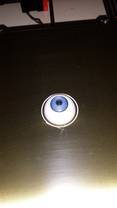
Start by printing the eyes.
I have printed eyes with 3 different colors and 4 color changes using Prusa ColorPrint.
Color change I used:
- z 0 – white
- z 13.9 – black
- z 14.1 – blue
- z 16.7 – black
If for some reason You don’t want or cant print multi colors (multi-color printer not needed) you can always try printing white and painting the colors.
I have try painting the colors and found that its much harder and does not look as good.
Making the capillary I used some red wool and Acrylic varnish see https://www.youtube.com/watch?v=q4vzEABlHMo (at 2:17).
I used glossy varnish to glue the wool and add a more realistic shine.
After the print is done its time to assemble Ball Buckle link and the Universal Joint.
You may need to cut Ball Buckle link screw to fit the holes (see pic).
A little superglue might be necessary depending on the fit.
Do not glue Universal Joint!
Step 5: 3d Printing
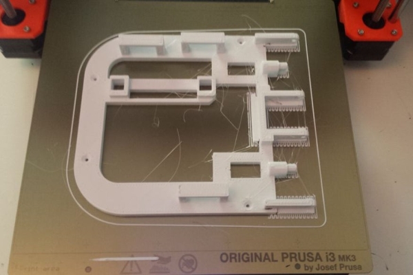
The rest of the prints are standard.
I use PETG but you can print in what ever you are custom to.
Print eyes and eyelids in highest detail you can. other parts don’t need high detail.
I have printed Base and Box with 0.8mm nuzzle 0.4 layer height to give them more strength but this is not necessary.
P.S if you did not experiment using different nuzzle size I encourage you to do so, Its a lot of fun.
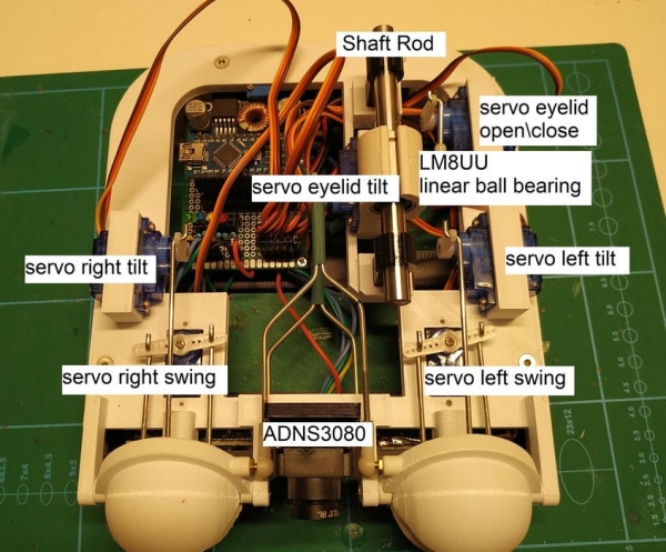
Step 6: Base Assembly
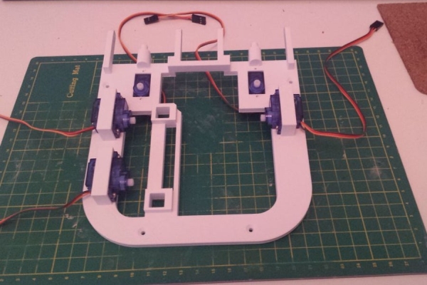
1- Attached SG90 9g Mini Micro Servos.
* notice orientation
** notice 2 front servos that controls swing action are mounted from bottom.
*** do not screw horns yet! Before screwing servo horns you need to set them at mid position (see init sketch in code part of this document)
2- Insert 2 rod holders.
Insert LM8UU Linear bearing inside mount.
Slide Shaft Rod through 1 holder into LM8UU all the way through second holder.
3- Cut Connecting Rods to size.
* This part is critical. Take your time and try to be precise as possible.
** Take into account the Z-bend. (z-bend pliers will make you job much easier and precise see:https://hobbyking.com/en_us/z-bend-pliers-heavy-duty-90-degree-up-to-1-16.html).
4- Connect rods.
Step 7: Electronics
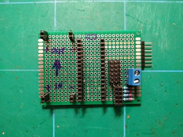
Create PCB.
XL4005
in:
12V
GND
out:
5V
GND
ADNS 3080 Wiring:
PIN_MISO – Pin 12
PIN_MOSI – Pin 11
PIN_SCK – Pin 13
PIN_MOUSECAM_RESET – Pin 9
PIN_MOUSECAM_CS – Pin 10
5V
GND
Servo Wiring:
pin 2 – right swing
pin 3 – right tilt
pin 7 – left swing
pin 6 – left tilt
pin 4 – eyelid tilt
pin 5 – eyelid open/close
5V
GND
LED Bar Wiring:
Pin A4
Pin A5
Pin A6
Pin A7
*Use 220 R resistor
5V
GND
IR LED Wiring:
12v
*Use 220 R resistor
GND
Step 8: Code
All sketches are available for download at:
https://github.com/Nimrod-Galor/eye-animatronics
Download as zip and unzip to you computer.
Upload init-servos.ino sketch into Arduino Bord.
This sketch will position all servos in mid position.
Now is the time to align servo horns and screw them.
After you screw all horns upload the eye-animatronics.ino to the Arduino.
Congratulations your eye animatronics project is Done.
Source: Motion Follow Animatronics Eyes