
Summary of Arduino Digital Switch Code
This article explains a basic Arduino project where a digital switch controls an LED. When the switch is pressed, it sends a signal to pin 2, causing the LED connected to pin 13 to turn on. The setup involves connecting the switch with a pull-down resistor and wiring the LED directly to the microcontroller.
Parts used in the Digital Switch Project:
- Arduino
- 5mm red LED
- 10kΩ resistor
- Switch
- Jumper wire
This is basic for your arduino projects, input switch read from digital input. When ever switch pressed, LED will turn on.
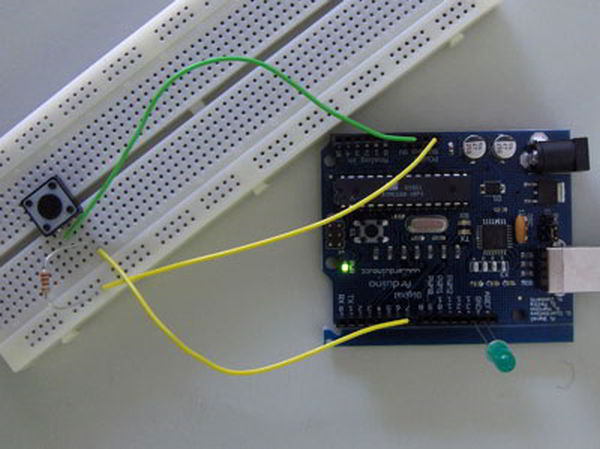
Instruction;
1) Connect cathode lead of LED (shorter lead) to ground pin and anode lead of LED (longer lead) to pin 13.
2) Add switch to breadboard, connect one of the switch lead to 5V pin.
3) Add 10kΩ resistor as in diagram and connect another switch lead to digital pin 2.
4) Connect GND to 10kΩ resistor.
Upload this code to your arduino
/*
  Digital Switch
  Reads a digital input on pin 2, when pressed LED light up.

  Coded by: arduinoprojects101.com
*/

void setup() {
  pinMode(2, INPUT);
  pinMode(13, OUTPUT);
}

void loop() {
  int switchValue = digitalRead(2);
  digitalWrite(13, switchValue);
}
pinMode(2, INPUT);
set digital pin 2 as input (from switch)
Major Components in Project
Parts List;
1) 1x Arduino
2) 1x 5mm red LED
3) 1x 10kΩ resistor
4) 1x Switch
5) Jumper wire
1) 1x Arduino
2) 1x 5mm red LED
3) 1x 10kΩ resistor
4) 1x Switch
5) Jumper wire
For more detail: Arduino Digital Switch Code
-
How do I connect the LED leads?
Connect the cathode lead (shorter) to ground and the anode lead (longer) to pin 13. -
What happens when the switch is pressed?
The LED will turn on because the code reads the digital input and writes that value to the output pin. -
Which pin should be set as input?
Digital pin 2 is set as input to read the signal from the switch. -
Where should the 10kΩ resistor be connected?
One end connects to GND and the other end connects to the switch lead that goes to digital pin 2. -
Which pin provides power to the switch?
One of the switch leads connects to the 5V pin. -
Can this code control multiple LEDs?
The provided text only describes controlling one LED connected to pin 13 based on the switch state. -
What is the purpose of the pinMode function in the setup?
It configures pin 2 as an input and pin 13 as an output for the program.
