
Summary of ADXL3xx Accelerometer using an Arduino
This tutorial explains how to read an Analog Devices ADXL3xx series accelerometer (e.g., ADXL320, ADXL330) using an Arduino and communicate the data to a computer. The device outputs analog voltage signals for each axis, which are read via the Arduino's `analogRead()` function. The circuit connects the sensor directly to the Arduino using specific analog pins for power, ground, self-test, and X, Y, Z-axis data.
Parts used in the ADXL3xx Accelerometer Project:
- Arduino Board
- ADXL3xx Accelerometer (e.g., ADXL320, ADXL321, ADXL322, ADXL330)
- Analog input pins on Arduino
- Digital output pins on Arduino
This tutorial shows you how to read an Analog Devices ADXL3xx series (e.g. ADXL320, ADXL321, ADXL322, ADXL330) accelerometer and communicate the acceleration to the a personal computer.

This tutorial was built using the breakout boards from Sparkfun. The adafruit accelerometer breakout board also works, though it must be wired differently.
The ADXL3xx outputs the acceleration on each axis as an analog voltage between 0 and 5 volts. To read this, all you need is the analogRead() function.
Circuit
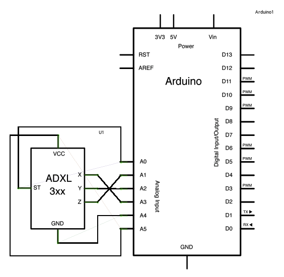
The accelerometer uses very little amperage, so it can be plugged into your Arduino and run directly off of the output from the Arduino’s digital output pins. To do this, you’ll use three of the analog input pins as digital I/O pins, for power and ground to the accelerometer, and for the self-test pin. You’ll use the other three analog inputs to read the acclerometer’s analog outputs.
image developed using Fritzing. For more circuit examples, see the Fritzing project page
Schematic:
Code
/*
ADXL3xx
Reads an Analog Devices ADXL3xx accelerometer and communicates the
acceleration to the computer. The pins used are designed to be easily
compatible with the breakout boards from Sparkfun, available from:
http://www.sparkfun.com/commerce/categories.php?c=80
http://www.arduino.cc/en/Tutorial/ADXL3xx
The circuit:
analog 0: accelerometer self test
analog 1: z-axis
analog 2: y-axis
analog 3: x-axis
analog 4: ground
analog 5: vcc
created 2 Jul 2008
by David A. Mellis
modified 30 Aug 2011
by Tom Igoe
This example code is in the public domain.
Hardware Required
- Arduino Board
- ADXL3xx Accelerometer
For more detail: ADXL3xx Accelerometer using an Arduino
- How does the ADXL3xx output acceleration data?
The ADXL3xx outputs the acceleration on each axis as an analog voltage between 0 and 5 volts. - Which function is used to read the analog voltage?
You need the analogRead() function to read the acceleration data. - Can other breakout boards be used besides Sparkfun?
Yes, the Adafruit accelerometer breakout board also works, though it must be wired differently. - How much amperage does the accelerometer use?
The accelerometer uses very little amperage, allowing it to run directly off the Arduino's digital output pins. - What pins are used for the self-test feature?
One of the analog input pins is used as a digital I/O pin for the self-test pin. - Which pins are assigned to the X, Y, and Z axes?
Analog 3 is the x-axis, Analog 2 is the y-axis, and Analog 1 is the z-axis. - Where can you find more circuit examples?
More circuit examples can be found on the Fritzing project page. - Who created the original example code?
The example code was created by David A. Mellis.