Summary of RFID cat door using Arduino
This project describes an RFID-enabled cat door controlled by an Arduino, allowing only pets with specific RFID tags to unlock and enter through a flap. It uses a custom large antenna to detect tags, solenoids to lock the door, a Hall effect sensor to detect door position, and an infrared proximity sensor to allow exit without RFID. The system distinguishes different tags for varied access and uses indicators like lights and timed unlocking to guide the pet. Components are connected to the Arduino, and soft padding is used to protect the cat’s tail.
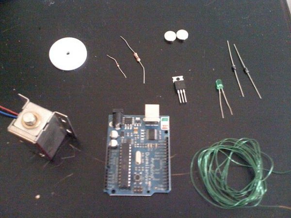
Parts used in the RFID Cat Door:
- Arduino Duemilanove
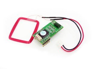
- 5V RF reader module (e.g., Seeed Studio 125Khz UART)
- RF tags (35mm disc shaped)
- 24 gauge magnet wire (about 86 feet)
- Sharp GP2D12 infrared proximity sensor
- Two 12V electronic cabinet locks (solenoids)
- 12V DC power supply
- Two TIP120 Darlington transistors
- Hall-effect sensor
- Magnets for Hall-effect sensor activation
- 100 Ohm resistor
- Four 2 KOhm resistors
- Two pushbuttons
- LED
- Hinge (with limited lateral movement)
- 1/8" thick Plexiglas pieces (6" x 9" and 6" x 3")
- Hookup wire (including ~27" extra thin 26 AWG wire)
- Nuts, bolts, and serrated washers
- Rubber isolation strip or soft padding material for door edges
Intro: RFID Cat Door
Only the pet with the correct RFID tag can unlock this specific cat door/flap. Arduino is responsible for overseeing the process. It features a custom antenna large enough to function as a gate, enabling the animal to easily and consistently activate it. Some methods and techniques are borrowed from my previous project, the RFID cat feeder. The feeder controls access to a food bowl, while the door controls access to an entire room. The latest code can also distinguish between tags so that the system can behave differently for different users.
RFID door (entering) from champenoise on Vimeo.
How it works:
1. In the beginning the door is locked, cat is outside
2. Cat walks up to the gate, RF tag gets read within about 4 inches
3. Door unlocks and a light comes on.
4. Timer ensures that door stays unlocked long enough to give cat a chance to respond
5. Cat pushes open the flap and enters
6. Flap falls back, activates Hall effect sensor, and the door locks
7. Going from the inside out, an infrared proximity sensor detects the presence of an animal if within about 10 inches and unlocks the door.
The majority of animals will rapidly pick up on pushing the flap when they hear the click (lock) and see the light. Ensure that soft padding is applied to the edges of both the door and the doorway to prevent the tail from getting trapped. Just a couple of bad experiences could be sufficient to discourage the cat from ever entering that place again.
The electronics are displayed unenclosed, but it is recommended to enclose them once finished. This is not elaborated on in this Instructable.
Step 1: Parts list
– Arduino Duemilanove
– 5V RF reader module (Seeed Studio 125Khz UART or equivalent. Most readers come with a small antenna. To use the custom made antenna discussed here, you need a reader that allows connecting an external antenna)
– RF tag (I used these 35mm disc shaped ones)
– About 86 feet of 24 gauge magnet wire (longer than the piece shown in the photograph)
– Sharp GP2D12 infrared proximity sensor
– Two 12V electronic cabinet locks (Nordson electronic). Solenoids, basically.
– One 12V DC power supply
– Two TIP120 Darlington transistors
– One Hall-effect sensor
– One or more magnets to activate Hall-effect sensor over a range of about 2cm
– One 100 Ohm resistor
– Four 2 KOhm resistors
– Two pushbuttons
– One LED
– One hinge (one that moves easily but without much lateral movement, for precision)
– One 6″ x 9″ piece of 1/8″ thick Plexiglas and perhaps another piece of about 6″ x 3″ to mount the locks
– Hookup wire, including about 27″ extra thin (26 AWG or thinner)
– Nuts, bolts and serrated washers
– Rubber isolation strip or other soft material for padding the edges of the door and door post
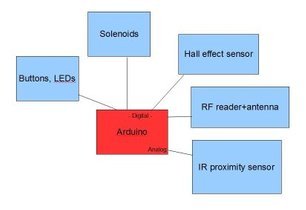
The system comprises several ‘modules’ (solenoids, RF reader, and so on). One of the pictures here shows the basic plan with the modules connected to the Arduino (the electronics). In the next steps the mechanical parts and each of the modules will be discussed in detail.
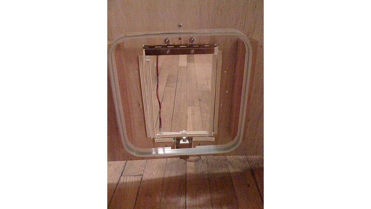
Step 2: Make the door
The entryway includes a Plexiglas panel connected to a hinge. At the bottom, two solenoids will be positioned beside the flap on the doorframe to stop unauthorized animals from getting in. Quite straightforward. Just keep in mind a couple of important factors:
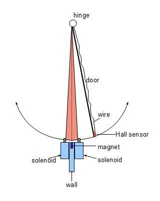
Make sure the flap is placed in the middle between the two solenoids when not in use. The picture is situated inside the red area encircling the dashed line at the middle. To achieve this, it is advantageous to not have any heavy items on one side and to utilize a low-friction hinge.
It is advantageous to have a hinge that has limited side-to-side movement (motion occurring within the same plane as the wall). This will help guarantee the operation of the hall-effect sensor, which is a switch activated by a magnet. I will explore this in more detail in the next step …
The door needs to be durable but also light so it can be easily pushed and to avoid injury if a tail gets caught. Round off the corners and add padding to the edges and door post to minimize tail problems.
Step 3: Make an antenna
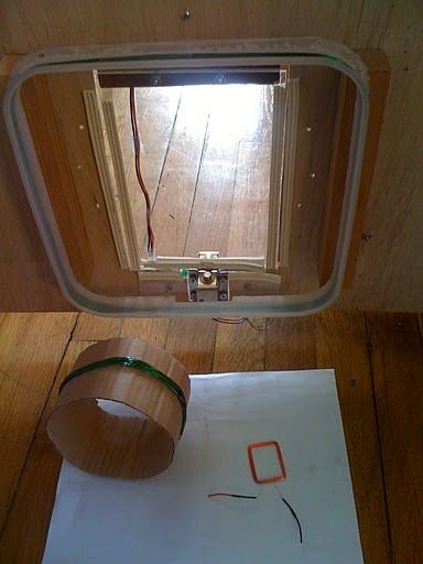
The antenna is nothing more than a coil of magnet wire connected to the RF reader. Most RF readers come with an antenna, but some allow the use of an external antenna. For this project I made a square antenna of 10 x 10 inches by winding 24 gauge magnet wire 24 turns around a sawed off bucket to make it sturdy. The distance between turns has to be as small as possible. I mounted the thing on the plywood with two pieces of wood as spacers to make it stand off from the wall a bit so the cat could activate it farther from the wall. The 35mm disc tags that I use are read up to 4 inches of the plane of the coil. The RF reader and antenna are powered with the 5v from the Arduino. Even though the Arduino works fine with just the USB cable, the RF reader works better when the Arduino is plugged into the wall with the 9v power adapter.
More info about coil antennas:
Microchip Inc. Antenna circuit design for RFID applications (pdf)
Step 4: Hook-up the RF reader
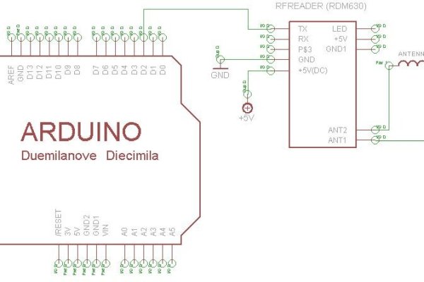
The project consists of multiple ‘modules’ that must be linked to the Arduino and evaluated in advance. Start by establishing a connection with the RF reader. The 5v output from the Arduino can power it, while a digital port (like 2) can be employed for signal reception. I used an RDM630 that has pins for a LED that is not being used. It has a RX pin for transmitting data back to the RF reader, but I opt not to use it. Attach your antenna, acquire a tag, and use the Arduino’s serial monitor to verify detection. You are now able to improve the antenna by testing out various adjustments such as adding or removing turns, trying different shapes, and so forth. Try using a 9v power source for the Arduino instead of USB, since USB didn’t work for me at least. You can choose to download the file ‘rfid3.pde’ for testing purposes. The code requires downloading NewSoftSerial.h from this location.
Step 5: Add solenoids
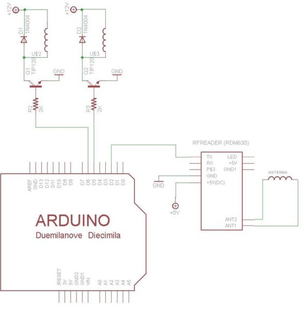
Hook-up the solenoids up to the Arduino as in the schematic: connect the TIP120s to digital ports 5 and 6 with 2k resistors in between. One pin goes to ground, the other goes to the solenoid, with a diode across it (make sure you get the polarity right), and to the 12v supply in the end. The other wire of the power supply is ground. Connect that to the other grounds. Just connect all grounds of all components including the Arduino together. Over here you can download code to specifically test the two solenoids
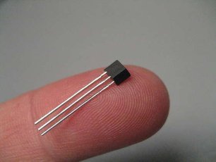
Step 6: Add Hall effect sensor
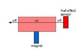
The Hall effect sensor’s function is to ascertain whether the door is centrally located, implying that it is within a suitable range for the locks to be engaged. Additional possible options consist of rotary encoders, touch sensors, and beam break sensors. I chose a Hall effect sensor primarily because it is frictionless, can be completely covered, and I was curious about how it works.
I chose not to use magnets on the door to prevent adding weight, so I put the switch on the door and the magnets in the door frame instead. I had to use a slender, very flexible wire to keep the flap from shifting because it was too stiff. The Plexiglas simply has the sensor and wire attached with tape. I possess a set of tiny magnets attached to the door frame. The sensor is 5mm away from the magnets at the closest point. The distance is roughly about 3 centimeters.
Link the signal pin of the Hall sensor to pin 4, then link it to 5v through a 100 ohm resistor. Join the ground pin with the other ground pins and connect the VCC pin to a 5-volt power source. Connect a green LED and a 220 ohm resistor to digital pin 7.
Download Hall_effect.pde to test this part of the system.
proximity sensor
power supply
Darlington transistors
pushbuttons
Step 7: Add Proximity Sensor
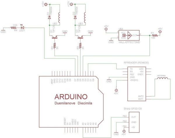
I was only concerned with which cat comes in and any animal can leave in this system. Therefore, I only required RFID on one side. The door must be able to open for any animal that comes from the opposite direction. The IR proximity sensor functions effectively.
Attach the output pin of a Sharp GP2D12 sensor to Analog port 0, connect the ground pin to the remaining ground pins, and link the vcc pin to a 5v power source.
Download IR_test_analog.pde to test this part of the system
Step 8: Add Two Buttons and Load Final Code
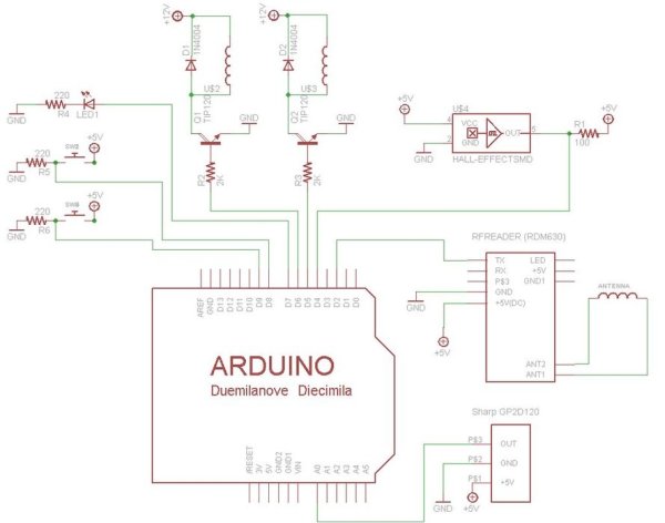
Finally you can add buttons to open the locks manually (see schematic). .
In the final code downloadable here, I stored the value of two tags worn by the our animals, one with and one without access. When the animal without access tries to get in, the door is locked immediately.
byte goodcode[6] = {0x1C, 0, 0xFC, 0xB2, 0x90};
byte badcode[6] = {0x16, 0, 0x78, 0xE7, 0xFE};
You must locate the tag codes being used and input them into the arrays ‘goodcode’ and ‘badcode’. In this programming language, hexadecimal values must be preceded by ‘0x’.
Lowering the open time (adjusting the variable ‘open_time’ to a lower value) may be helpful if you want to avoid tagging the second cat, even though this means the cat with access will need to react faster.
Enclosing the electronics is a helpful recommendation, but it will not be addressed in this guide.
If your antenna’s broad coverage extends into the safe zone, you might need to recalibrate the antenna and proximity sensor to avoid unintentional triggering of the RF reader from within. The cat must be detected first by the proximity sensor if it is inside and wants to leave. If that happens, it’s okay because the RF reader isn’t authenticated in that part of the program.
Source : RFID cat door using Arduino