Summary of RGB Color Detector Using TCS3200 Sensor Module
This project uses an Arduino Uno R3 with a TCS3200 color sensor to detect basic colors (red, green, blue) from LEDs such as a common-cathode RGB LED. The TCS3200 converts light intensity to frequency via an 8x8 photodiode array with selectable color filters. The system displays RGB intensity and color name in the Arduino serial monitor and lights the matching LED color. The design includes a power regulator chain, PCB layout, and Arduino sketch (TCS3200.ino) uploaded via Arduino IDE.
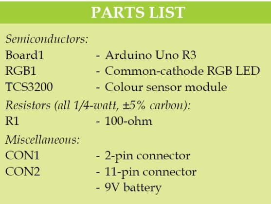
Parts used in the RGB Color Detector Using TCS3200 Sensor Module:
- Arduino Uno R3 board (ATmega328/ATmega328P)
- TCS3200 color sensor module (SEN0101)
- Common-cathode RGB LED
- 9V power supply
- Bridge rectifier
- 5V voltage regulator
- LM1117 voltage regulator (for 3.3V)
- PCB (single-side) and associated PCB components
- Connecting wires and headers
- Computer with Arduino IDE (for uploading sketch)

This Color Detector utilizes an Arduino Uno R3 and TCS3200 color sensor module. Color identification and detection can be beneficial for food-processing units, color printer applications, paint-mixing applications, and other industrial applications such as robotics.
This project is designed to identify basic colors (red, green, and blue) that are present in LEDs in a single package, such as a common cathode or common-cathode RGB LED. By adjusting the Arduino code, we have the ability to produce unique colors in addition to showcasing primary colors. The project showcases how to connect the TCS3200 sensor, Arduino Uno, and common-cathode RGB LED.
Figure 1 displays the TCS3200 color sensor module (SEN0101).
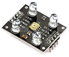
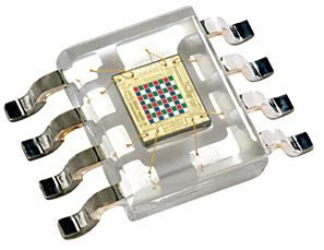
Fig. 2 displays a close-up look at the RGB arrays at a microscopic level. The square boxes can be observed within the eye sensor on a microscopic scale.
These square boxes are grids made up of the RGB matrix. Every box has three sensors inside, one for detecting the intensity of red light, another for green light, and a third for blue light. It surpasses the TCS230 color sensor module in performance. With a precise programming code, this sensor can be utilized to recognize various colors.
Circuit and working
Fig. 3 shows the circuit diagram of the RGB color detector using TCS3200.
It works off 9V power supply connected across connector CON1. However, an Arduino Uno board requires only 5V. So it has a bridge rectifier with a regulator that converts 9V to 5V logic, which can further be converted to 3.3V with the help of LM1117 voltage regulator.

Circuit diagram of the RGB color detector using TCS3200
The central component of the circuit is the Arduino Uno R3 board, which features either the ATmega328 or ATmega328P microcontroller (MCU). There are 14 I/O pins and six analogue input pins, as well as 32k flash memory, a 16MHz crystal oscillator, USB connection, power jack, ICSP header, and reset button.
The TCS3200 module includes eight pins, as illustrated in Figure 4. This module comprises programmable color light-to-frequency converters that integrate configurable silicon photodiodes and current-to-frequency converter on one monolithic CMOS integrated circuit. The output consists of a square wave with a 50 percent duty cycle, where the frequency is directly correlated to the brightness of light.
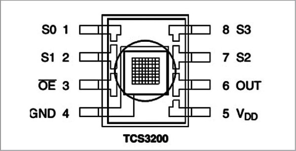
Pin diagram of the TCS3200 color sensor module
Digital inputs and outputs enable a direct connection to the MCU or other logic circuits. Output enable (OE) causes the output to enter a state of high impedance when multiple units are connected to an MCU input line. The light-to-frequency converter in TCS3200 detects light using an 8×8 array of photodiodes. There are 16 photodiodes with blue filters, another 16 with green filters, and 16 more with red filters, while the last 16 have no filters and are clear.
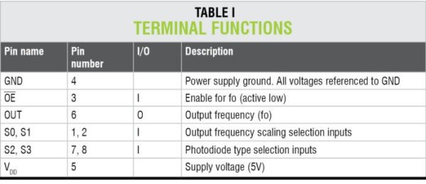
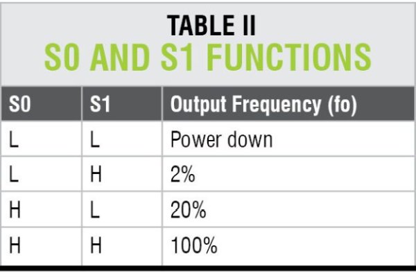
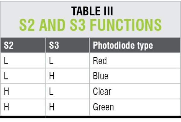
All photodiodes of the same color are connected in parallel. Pins S2 and S3 of TCS3200 are used to select the group of photodiodes (red, green, blue and clear) that are active. The detailed pin description is shown in Tables I, II and III, respectively.
Each sensor array in these three arrays is selected separately, depending on the requirement. Hence, it is known as a programmable sensor.
The module can be used to sense a particular color only. It contains filters for selection purpose. There is a fourth mode with no filter. With no filter, the sensor detects white light.
Construction and testing
An actual-size, single-side PCB layout of the RGB color detector using TCS3200 is shown in Fig. 5 and its component layout in Fig. 6.
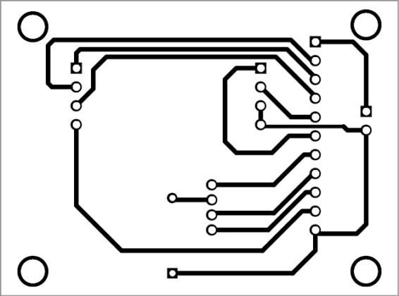
Actual-size PCB layout of the RGB color detector using TCS3200

Component layout of the PCB
The project functions easily as it involves a fundamental circuit for connecting a TCS3200 sensor. When the sensor is placed close to red color, it detects the color using photodiode arrays, displaying the RGB color intensity value and color name in the Arduino serial monitor window. Simultaneously, there is a red LED illuminated within the RGB LED. In the same way, the Arduino serial monitor displays the remaining two colors (green and blue) and the RGB LED lights up accordingly.
Software
Arduino programming language is used to write software. Arduino IDE software is used to program the Arduino Uno Board1. The ATmega328P on the Arduino Uno board is equipped with a pre-installed bootloader, enabling you to upload new code without the need for an external hardware programmer.
Plug in Arduino board to the computer and choose the right COM port within Arduino IDE. Build the code (TCS3200.ino). Choose the appropriate board from the Tools→Board dropdown menu in Arduino IDE and upload the code.
Put the software into the MCU’s internal memory. The core of the system is the sketch, which performs all key functions. Arduino IDE 1.6.4 is used to compile and upload it.
Download source code
In this project, external header files are not required for programming. It is a simple way to detect RGB color intensities on the serial port. The author’s prototype is shown in Fig. 7.
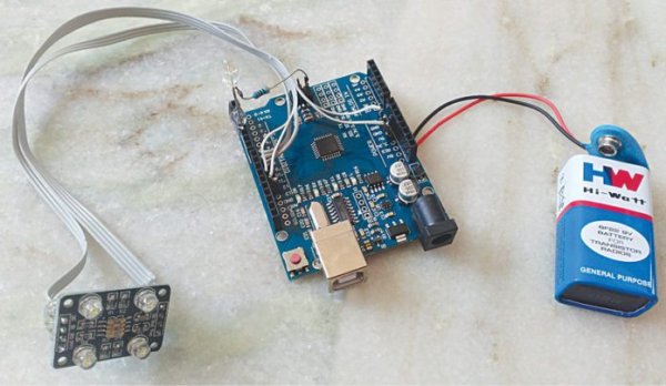
Author’s prototype
Source :RGB Color Detector Using TCS3200 Sensor Module
- What microcontroller does the project use?
The project uses an Arduino Uno R3 with an ATmega328 or ATmega328P microcontroller. - Which color sensor module is used?
The project uses the TCS3200 color sensor module (SEN0101). - How does the TCS3200 output color information?
The TCS3200 outputs a square wave whose frequency is directly proportional to light brightness, derived from selected photodiode arrays. - Can the sensor select different color photodiode groups?
Yes, pins S2 and S3 select the photodiode group (red, green, blue, or clear). - What colors can the project identify by default?
The project is designed to identify basic red, green, and blue colors. - How are detected colors displayed?
RGB intensity values and the color name are displayed in the Arduino serial monitor, and the corresponding LED lights. - What power supply arrangement is used?
The system uses a 9V supply with a bridge rectifier and regulator to provide 5V, and LM1117 for 3.3V if needed. - Is external header or library required for programming?
No external header files are required; the project uses a simple Arduino sketch (TCS3200.ino). - Which software and IDE are used to upload the code?
Arduino IDE (example version 1.6.4) is used to compile and upload the code to the Arduino Uno.