
Summary of DIY Time Control Machine
This article details a DIY project to build a "Time Machine" glove that creates a visual illusion of stopping time. The device utilizes an Arduino Nano, high-power LED, and motion sensors to synchronize light pulses with movement, achieving a smooth effect visible to the naked eye. Construction involves assembling power and logic circuits, mounting components on a glove with thermal management for the LED, and flashing custom code from GitHub.
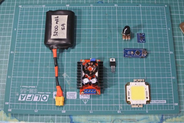
Parts used in the Time Control Machine:
- Glove
- 100W White LED
- Optics (Lenses)
- DCDC Boost Converter
- Arduino NANO
- Accelerometer (IMU)
- Potentiometers
- Lithium Battery
- 10 k and 100 Ohm resistors
- MOSFET (various models listed)
- Copper Cooling Plate
- Thermal Paste
- Cable Ties and Velcro Strip
This project is about how to make a time machine! This machine looks like a glove, and can “stop” any moving subject. At first, watch a video with some demonstration and experiments, guess how it works, and then read about how to make it =)
This effect looks like better in real life (by naked eye, not through a camera), without black lines. Smooth perfect time stop effectc!! IT IS REAL “OH MY GOD” REACTION!
Step 1: All We Need
Generally this project is about Arduino, high-power LED and some tricky magic with soldering iron. Here is some list with links to AliExpress
- Glove http://ali.pub/1ypcm5
- LED 100W, white http://ali.pub/1ypcoa
- Optics http://ali.pub/1ypda2 http://ali.pub/1ypdc0
- DCDC boost http://ali.pub/1ypda2 http://ali.pub/1ypdfb
- Arduino NANO http://ali.pub/1ypda2
- Accelerometer http://ali.pub/1ypda2
- Potentiometers http://ali.pub/1ypda2
- Lithium battery http://ali.pub/1ypda2
- 10 k and 100 Ohm resistors
- MOSFET. Use one of this: IRF3704ZPBF IRLB8743PBF IRL2203NPBF IRLB8748PBF IRL8113PBF IRL3803PBF IRLB3813PBF IRL3502PBF IRL2505PBF IRF3711PBF IRL3713PBF IRF3709ZPBF AUIRL3705N IRLB3034PBF IRF3711ZPBF
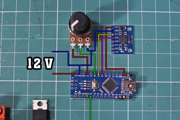
Step 2: Wiring
Step 3: Assembling Power Part
At first connect battery, DCDC and MOSFET. Also you need to tune DCDC to 34 V output voltage.
Step 4: Assembling Logic Part
Connect potentiometer and IMU to Arduino
Step 5: Fixing on Glove
Fix all parts on glove, using cable ties and Velcro strip.
Step 6: LED and Cooling Plate
Fix LED on copper plate, and don’t forget to smear thermal paste between them.
Step 7: Fixing LED
Finely, place LED on it’s place on glove in order:
- Metal mount
- Glove fiber
- Lense
- LED
- Cooling plate
Step 8: Flashing Arduino
You can download sketch and schemes on project’s project page on GitHub, also Arduino code you can find in attached files.
Read more: DIY Time Control Machine
- How does this time machine work?
The effect works by using an Arduino, accelerometer, and high-power LED to create a visual illusion of stopped time through synchronized light pulses. - Can I see the effect without a camera?
Yes, the effect looks better in real life by the naked eye without black lines when viewed directly. - What voltage should the DCDC converter be tuned to?
You need to tune the DCDC converter to a 34 V output voltage. - Which specific MOSFET models are recommended?
Recommended models include IRF3704ZPBF, IRLB8743PBF, IRL2203NPBF, and several others listed in the parts section. - How do you attach the LED to the glove?
The LED is fixed on a copper plate with thermal paste, then placed on the glove in order of metal mount, glove fiber, lens, LED, and cooling plate. - Where can I find the Arduino code and schemes?
The sketch, schemes, and code can be downloaded from the project page on GitHub or found in attached files. - What is used to secure the parts on the glove?
All parts are fixed on the glove using cable ties and Velcro strips. - Does the project require soldering skills?
Yes, the project involves tricky magic with a soldering iron to assemble the components.