
Summary of Spinning or Rotating LED Display using Arduino POV
This project builds a rotating LED display (persistence-of-vision sign) using an Arduino Pro Mini on a lightweight PCB, seven LEDs, an IR LED and photodiode feedback pair, and a small DC gear motor. The rotating PCB displays blinking LED patterns as alphanumeric text; code can be adapted for other languages. The design emphasizes a lightweight etched PCB for high-speed rotation and recommends upkeep of the motor and rotating assembly for reliable signage use.
Parts used in the Rotating LED Display:
- Arduino Pro Mini
- Seven LEDs
- IR LED
- Photodiode
- Tiny DC gear motor
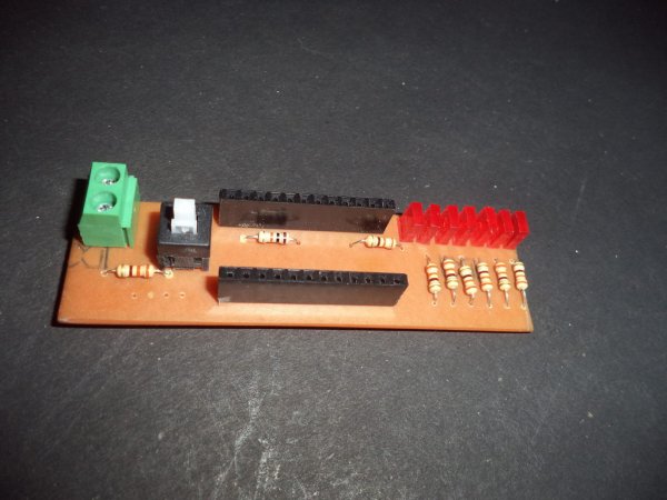
- Custom PCB (designed in Eagle CAD, suitable for etching)
- Connection wires / single LED line to Arduino
- Mounting hardware for rotating assembly
Designing a Spinning/Rotating LED Display
In this project, we will demonstrate how to create a basic “Rotating LED Display” (commonly referred to as Spinning LED Display) using Arduino. The idea to start this project sparked in my mind after I noticed a product in the market that featured a clearly visible text message on a “Rotating LED Strip”.
After that, I planned to make this project myself and Arduino is a good choice to build this spinning led display.
For this project, I designed PCB using Eagle CAD software. The reason to choose Eagle was to build a lightweight PCB, as there is high speed rotation involved in the project, and the PCB will be a part of the rotating module. In this circuit, “Arduino pro mini” is used because it is very small and powerful board.
Seven LED’s, as well as a duo of IR LED and a Photodiode, are also utilized. IR LED and Photo diode are employed in creating a feedback system to provide the real position of the rotor to Arduino. The Arduino board is connected to a single line of LEDs. A tiny DC gear motor is employed to spin this circuit; and as the circuit rotates, the LED’s display a blinking pattern representing English alphabets. The code can be adjusted to show different languages.
The operation of the Rotating LED Display is fascinating and it can be utilized for decorative purposes, enabling the creation of stunning designs and graphics with this remarkable project. This signage can be utilized in public areas such as train/bus terminals and airports as a billboard due to its cost efficiency in construction. Maintaining the gear motor and rotating assembly is essential.
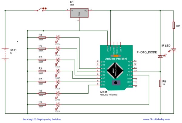
Circuit Diagram
Circuit diagram is shown above. I also designed a PCB on EAGLE and the files are given below. it would be better to use etched PCB. PCB Etching process is a simple task, you can learn this from our blog. For PCB etching refers the figure given below.
Read more: Spinning or Rotating LED Display using Arduino POV
- What microcontroller is used in the project?
The project uses an Arduino Pro Mini as the microcontroller. - How many display LEDs are used?
Seven LEDs are used for the display line. - How is rotor position detected?
An IR LED and a photodiode form a feedback system to provide rotor position to the Arduino. - What spins the PCB and LEDs?
A tiny DC gear motor is used to spin the rotating circuit. - Which CAD software was used to design the PCB?
The PCB was designed using Eagle CAD software. - Is PCB etching recommended?
Yes, the article recommends using an etched PCB for a lightweight rotating module. - Can the displayed text be changed to other languages?
Yes, the code can be adjusted to show different languages. - Where can this signage be used?
The article suggests decorative use and public areas like train/bus terminals and airports as economical signage. - What maintenance is important for the project?
Maintaining the gear motor and rotating assembly is essential for reliable operation.