Summary of 3D AIR mouse | Arduino + Processing
This article details a DIY 3D air mouse project by an industrial design student, enabling intuitive 3D object rotation in CAD software like SolidWorks. The system uses an Arduino to process data from a 3-axis compass sensor and an optical detector that triggers "3D mode" when the mouse is lifted. A Processing sketch translates these movements into on-screen commands, offering a more natural alternative to traditional 2D mouse inputs for engineering tasks.
Parts used in the 3D AIR mouse:
- A used computer mouse with sufficient internal space
- HMC634 Compass Module with Tilt Compensation
- Logic Level Converter (5V to 3.3V)
- Large Optical Detector / Phototransistor
- One ultra-bright LED
- Two resistors (100Ω and 100KΩ)
- Arduino board (Diecimila or Duemilanove model)
- Processing software
- Soldering iron and extra wires
- Hot glue and tiny screws
- 6mm diameter wooden anchor pieces
- Cutting knife and file for shaping plastic
3D AIR mouse | Arduino + Processing
I’m an Industrial design student, and last year as part of a course called “Technology as RAW materiel” I built this project as my final work.
I work most of the time with SolidWorks, a CAD software for design and engenering. Rotating a solid body on the screen is done using the middle mouse button. I was looking for something more intuitive.
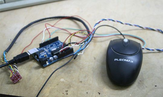
This is how I ended up doing the 3D air mouse, where the actual rotation of an object is done by moving the mouse in mid air on all 3 axis – the same way you would rotate the object if you held it in your hand.
I used the Arduino, a couple of sensors and a Processing sketch.
NOTES:
– As of now, this is only a demonstration of the concept, as there is no actual plug-in to work with SolidWork (but of course, feel free to write one if you know how 🙂
– Since all the hardware wasn’t mine, the actual 3D mouse is long gone, and I’m using some photos and a video to try and make some sense in all this, and to give you some idea if you want to try and build one yourself…
Enjoy it… (It’s my first Instructable)
Here’s the a video demo of the finished project
Step 1: Hardware and stuff
Stuff you’ll need:
* A mouse – a used one is better (only because it’s used and cheaper), any mouse should do. You do need to have some space to house the sensors and some extra wires, so don’t go for extra slim / extra tiny mice.
* Compass Module with Tilt Compensation – HMC634 – This is the 3 axis sensor, bought at SpurkFun for ~$149
* Logic Level Converter – A MUST! Since the Arduino is 5V and the 3 axis sensor is 3.3V, you need one of those to convert the 5V into 3.3V. It has a big name, but only cost $1.95 at SpurkFun.
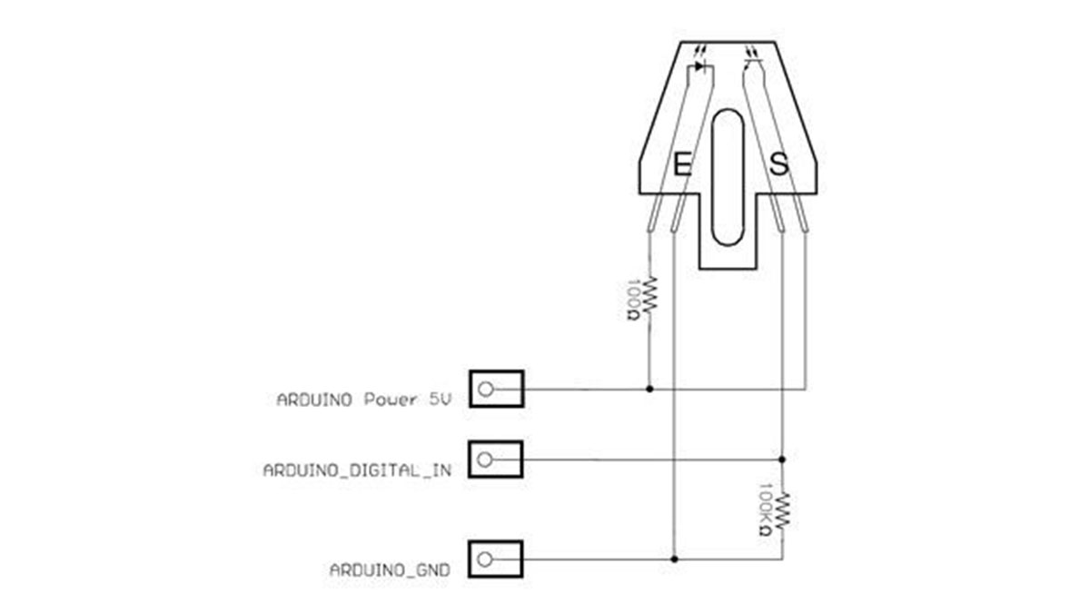
* Large Optical Detector / Phototransistor – This is a simple optical sensor, used in this project to detect when the mouse is being lifted off the work surface. Bought at SpurkFun for $2.25
If you don’t have enough space to house this one inside your chosen mouse, you can use this one, smaller and cheaper.
One (1) LED – never mind the color, ultra bright will work better.
* 2 Resistors – One (1) x 100Ω and One (1) x 100KΩ (For the optical sensor)
* Arduino board – DA! I used the Diecimila model. A newer Duemilanove is avalilable at SpurkFun for about $29.95 (Should work too) + Arduino software installed.
* Processing software installed.
* The project’s source code (Don’t worry, you’ll get to download it in a sec.)
Plus:
Some hot glue (to fix things in place)
A couple of tiny screws.
About 10cm of a 6mm (Dia.) wooden anchor.
Some extra wires.
Soldering iron.
Something to cut the plastic with, I used a cutting knife and a file (FOR shaping).
(“Ok, don’t hate me for this step, English is my 2nd language, if I got this one wrong, I’m sorry, I’m sure you’ll understand what I’m taking about in a sec. when you’ll see it in pictures”)
Step 2: Electronics
The attached source code can only work if you use the same pin numbers I did, but feel free to change those when connecting as long as you change the appropriate numbers in the code.
Connecting the 3 axis sensor to the logic level converter:
Sensor VCC -> Arduino 3V3
Sensor GND -> Arduino Gnd
Sensor SDA -> Converter TXI (Chan1)
Converter TXO (Chan1) -> Arduino ANALOG IN 4
Sensor SCL -> Converter TXI (Chan2)
Converter TXO (Chan2) -> Arduino ANALOG IN 5
Converter GND (at least one of them) -> Arduino Gnd
Converter HV -> Arduino 5V
Converter LV -> Arduino 3V3
See attached image
Digital in = Pin 11 on the ArduinoLED:
GND to some GND (I used one of the optical sensor)
+ to Arduino PIN 13 (This was done since this pin already have an on-board resistor, if you use a different one, make sure to use a resistor so you wont burn the LED)
Step 3: Preparing the Mouse
This is where the sensors find their place inside the mouse’s housing.
Find the best place to fix the 3 axis sensor. Make sure is it leveled and mind the orientation (You’ll know when you’ll have the sensor in hand)
You can fix it any way you like, I used 2 short pieces of the wooden anchor, drilled to accept the 2 tiny screws, and hot glued to the mouse’s main board.
For the optical sensor, shape a rectangular hole at the bottom of the mouse, the idea is to have the sensor “see” the table the all time. When the mouse is lifted and the sensor state is “open” (no table to see) the mouse switches into 3D mode (runs the Processing sketch)
Shape another hole for routing the extra wires (from the sensors to the Arduino) out of the plastic housing. Mine was located on the right hand side of the mouse.
Fix the LED where is will show. In this project the LED is the 3D-mode indicator. I places mine next to the silicone mouse wheel. When the mouse is lifted, the wheel had a nice blue glow.
Detector
Phototransistor
Compass Module
Compensation
sensors
- How does the mouse switch to 3D mode?
The optical sensor detects when the mouse is lifted off the surface; when the sensor state is open, it switches to 3D mode. - Why is a Logic Level Converter necessary?
It is required because the Arduino operates at 5V while the 3-axis sensor requires 3.3V. - Can I use any type of mouse for this project?
Any mouse works as long as it has enough internal space to house the sensors and extra wires. - What role does the LED play in the project?
The LED serves as a 3D-mode indicator that glows when the mouse is lifted. - Does the code work with different pin numbers?
The attached source code requires specific pin numbers unless you modify the code to match your new connections. - What software is needed to run the project?
You need the Arduino software installed on the board and the Processing software for the sketch. - How are the sensors secured inside the mouse?
The author used hot glue and short pieces of wooden anchors drilled to accept tiny screws. - Is there a plugin available for SolidWorks?
No, the article states this is only a concept demonstration with no actual SolidWorks plugin currently available.