
Summary of 1.2V-25V/10A Adjustable Power Supply Using Power Op-Amp
This article describes a compact, adjustable power supply circuit utilizing the OPA549 power operational amplifier. It delivers an output voltage ranging from 1.2V to 25V with an adjustable current limit between 0A and 10A. The design accepts a 30V DC input supply and a 5V logic supply, featuring onboard trimmer potentiometers for manual adjustments and an LED indicator for thermal shutdown status. Due to its high current capability, the circuit requires a large heat sink for optimal performance.
Parts used in Adjustable Power Supply Using OPA549:
- OPA549 Power Op-Amp
- Input Supply (30V DC)
- Logic Supply (5V DC)
- Trimmer Potentiometers (Voltage and Current)
- LED D1 (Over Temperature Indicator)
- Screw Terminals (Input and Output Connections)
- Large Heat Sink
- Digital-to-Analog Converter (DAC) Option
- Logic Gate (for E/S pin indication)
This is a small size power supply based on OPA549 power op-amp that provides output voltage 1.2V to 25V with 0 to 10A adjustable current limit. Two onboard trimmer potentiometers provided to adjust the voltage and current, LED D1 is over temperature indicator. The circuit works with input supply of 30V DC and logic supply 5V DC. IC requires large size heat sink to work with full 10A current range.
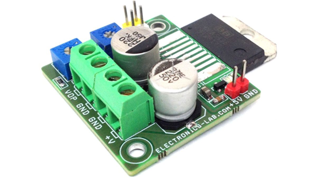
Screw terminals for input and output connections are provided. The OPA549 is a low-cost, high-voltage/high-current operational amplifier ideal for driving a wide variety of loads. This laser-trimmed monolithic integrated circuit provides excellent low-level signal accuracy and high output voltage and current. The OPA549 operates from either single or dual supplies for design flexibility. The input common-mode range extends below the negative supply. The OPA549 is internally protected against over-temperature conditions and current overloads. In addition, the OPA549 provides an accurate, user-selected current limit. Unlike other designs which use a “power” resistor in series with the output current path, the OPA549 senses the load indirectly. This allows the current limit to be adjusted from 0A to 10A with a resistor/potentiometer, or controlled digitally with a voltage-out or current-out Digital-to-Analog Converter (DAC). The Enable/Status (E/S) pin provides two functions. It can be monitored to determine if the device is in thermal shutdown, and it can be forced low to disable the output stage and effectively disconnect the load. The OPA549 is available in an 11-lead power package. Its copper tab allows easy mounting to a heat sink for excellent thermal performance. Operation is specified over the extended industrial temperature range, –40°C to +85°C.
Features
- Input Supply 30V DC
- Logic Supply 5V DC
- Output 1.2V to 25V DC
- Load Current Limit Adjustable 0 To 10A
- Thermal Shutdown LED Indicator
A programmable source and sink power supply can easily be built using the OPA549. Both the output voltage and output current are user controlled. See Figure 12 for a circuit using potentiometers to adjust the output voltage and current while Figure 13 uses DACs (refer to datasheet). An LED connected to the E/S pin through a logic gate indicates if the OPA549 is in thermal shutdown.
Read more: 1.2V-25V/10A Adjustable Power Supply Using Power Op-Amp
-
What is the output voltage range of this power supply?
The circuit provides an output voltage ranging from 1.2V to 25V. -
How can the current limit be adjusted?
The current limit is adjustable from 0A to 10A using resistor/potentiometer combinations or digitally via a DAC. -
Does the OPA549 require a heat sink?
Yes, the IC requires a large size heat sink to work with the full 10A current range. -
What supplies are needed for the circuit to operate?
The circuit works with an input supply of 30V DC and a logic supply of 5V DC. -
Can the device detect thermal shutdown conditions?
Yes, an LED connected to the Enable/Status pin indicates if the device is in thermal shutdown. -
How does the OPA549 sense the load current?
The OPA549 senses the load indirectly rather than using a power resistor in series with the output current path. -
Is it possible to disable the output stage manually?
Yes, forcing the Enable/Status pin low disables the output stage and effectively disconnects the load.
