
Summary of Twitter Controlled Pet Feeder using an Arduino
Summary (under 100 words): This project modifies an automatic Amazon pet feeder so an Arduino with an Ethernet shield can trigger dispensing based on Twitter activity. Photoresistors and LEDs emulate the feeder's set and volume button presses; wiring taps the feeder PCB and battery power to run the Arduino. Steps include opening the feeder, exposing and wiring button traces, mounting sensors and LEDs, and connecting the Ethernet-enabled Arduino to monitor Twitter and activate dispensing.
Parts used in the Twitter-Controlled Pet Feeder:
- Automatic Pet Feeder Amazon
- 10K Ohm 1/4-Watt Carbon Film Resistor (2x)
- Arduino Ethernet Shield w/o PoE Module
- CdS Photoresistors 5 pack (4x used)
- Grid-Style PC Board
- White Super-bright LED Indicator (2x)
- Male Header Pins 40 Position
- D Alkaline Batteries (4x)
- 4.7K Ohm 1/4-Watt Carbon Film Resistor (2x)
- Current limiting resistors for LEDs (example: 100 ohm 1/4W)
- Drill
- Solder
- 22 Gauge Wire
- Optional: pushbuttons for troubleshooting
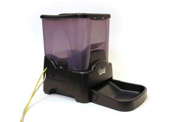
A great project for busy pet owners. This Twitter-Controlled pet feeder automatically dispenses food in response to activity on your Twitter account. The project is controlled by an Arduino and uses the Arduino Ethernet shield to receive data from Twitter. I hacked this automatic Pet Feeder from Amazon to build this project, but you could easily modify your own motorized feeder to work.
Parts List:
(1x) Automatic Pet Feeder Amazon
(2x) 10K Ohm 1/4-Watt Carbon Film Resistor (1 package) Radioshack #271-1335
(1x) Arduino Ethernet Shield w/o PoE Module Radioshack #276-130
(4x) CdS Photoresistors 5 pack (1 package) Radioshack #276-1657
(1x) Grid-Style PC Board Radioshack #276-147
(2x) White Super-bright LED Indicator Radioshack #55050633
(1x) Male Header Pins 40 Position Jameco #160882
(4x) “D” Alkaline Batteries (1 package) Radioshack #23-865
(2x) 4.7K Ohm 1/4-Watt Carbon Film Resistor (1 package)
(2x) current limiting resistors, see the sample calculation below
from the specs of the LEDs I used:
“Continuous forward current: 30mA”
“Forward voltage: 3.6V”
using the following relationship:
V(volts) = I(amps) * R(ohms)
rearranged to:
R = V / I
we can calculate the resistance as follows:
voltage across resistor = 5V – 3.6V = 14V
1.4V / 0.03A = 47ohms
I used 100 ohm 1/4W 5% Carbon Film Resistors Radioshack #271-1311 so that the LEDs wouldn’t be operating at their maximum ratings. Check the datasheet of the LEDs you use to calculate these values.
Additional Materials:
drill
Solder Radioshack #64-013
22 Gauge Wire Radioshack #278-1224
Step 1: Open pet feeder
Unscrew 8 screws from the base of the pet feeder and carefully lift the bottom panel of the feeder open. There are some wires which permanently attach the bottom panel to the body, be careful not to put too much strain on them.
Step 2: Unscrew pcb
Remove six small screws from control pcb. One of the screws is hidden under a small pcb on top of the main pcb. Once all the screws are removed, the pcbs should easily lift off the plastic enclosure.
Step 3: Schematic
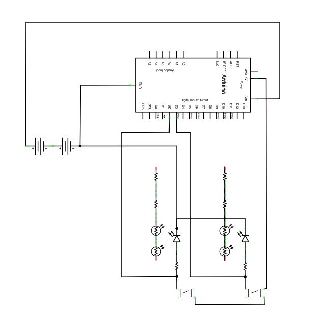
When the photoresistors are not exposed to light their resistance will be very high and the processor in the feeder will think that the buttons aren’t being pressed. By telling the arduino to light up some LEDs near the photoresistors, the resistance will decrease low enough for the feeder’s processor to think that the buttons are being depressed.
I’ve also attached two pushbuttons in the circuit so that I could manually turn the LEDs on for troubleshooting purposes. These buttons are not essential to the project (but useful).
I also be diverted some power from the feeder’s four D batteries to power the arduino.
 twitter feeder.fz243 KB
Step 4: Drill holes in pcb
Locate the “volume” and “set” buttons on the pcb (compare with the labels on the outside of the feeder enclosure). Remove the tape and small circular metal covering from these buttons (figure 2). You will see two exposed traces on each button. Each outer trace has two holes drilled in it (see figure 1). Drill two additional holes in the pcb, one in each of the inner circular button traces (figure 3).
Step 5: Solder wires to pcb
Solder four wires to the control pcb so each of the four exposed button traces has one wire electrically connected to it.
(2x) 10K Ohm 1/4-Watt Carbon Film Resistor (1 package) Radioshack #271-1335
(1x) Arduino Ethernet Shield w/o PoE Module Radioshack #276-130
(4x) CdS Photoresistors 5 pack (1 package) Radioshack #276-1657
(1x) Grid-Style PC Board Radioshack #276-147
(2x) White Super-bright LED Indicator Radioshack #55050633
(1x) Male Header Pins 40 Position Jameco #160882
(4x) “D” Alkaline Batteries (1 package) Radioshack #23-865
(2x) 4.7K Ohm 1/4-Watt Carbon Film Resistor (1 package)
(2x) current limiting resistors, see the sample calculation below
from the specs of the LEDs I used:
“Continuous forward current: 30mA”
“Forward voltage: 3.6V”
using the following relationship:
V(volts) = I(amps) * R(ohms)
rearranged to:
R = V / I
we can calculate the resistance as follows:
voltage across resistor = 5V – 3.6V = 14V
1.4V / 0.03A = 47ohms
I used 100 ohm 1/4W 5% Carbon Film Resistors Radioshack #271-1311 so that the LEDs wouldn’t be operating at their maximum ratings. Check the datasheet of the LEDs you use to calculate these values.
For more detail: Twitter Controlled Pet Feeder using an Arduino
- What does the project do?
The project makes an automatic pet feeder dispense food in response to activity on a Twitter account using an Arduino and Ethernet shield. - How does the Arduino simulate button presses on the feeder?
The Arduino lights LEDs near photoresistors so their resistance drops and the feeder's processor senses the buttons as pressed. - Can I modify my own motorized feeder instead of the Amazon feeder?
Yes, the article states you could easily modify your own motorized feeder to work. - Where does the Arduino get power in this project?
The author diverted some power from the feeder's four D batteries to power the Arduino. - What components are soldered to the feeder PCB?
Four wires are soldered to the exposed button traces for the set and volume buttons. - Do I need pushbuttons for the project?
No, the pushbuttons are optional and used only for manual troubleshooting. - How are holes made for wiring into the PCB buttons?
You drill holes in the outer and inner circular button traces to access the exposed traces for wiring. - What resistors are recommended for the LEDs?
The author used 100 ohm 1/4W resistors although a calculated 47 ohm was shown; check the LED datasheet to calculate values.