This post starts a small (or larger?) series of tutorials using the Arduino Motor/Stepper/Servo Shield with the FRDM-KL25Z board. That motor shield is probably one of the most versatile on the market, and features 2 servo and 4 motor connectors for DC or stepper motors. That makes it a great shield for any robotic project
The series starts with a tutorial how to drive two servo motors. And if this is not what you are expecting to do with this shield, then you can vote and tell me what you want to see instead on this motor shield :-).
OEM or Original?
The original Arduino Motor/Stepper/Servo Shield is available from Adaftruit Industries and costs less than $20. I’m using a OEM version, see this link. The functionality is the same, except that the OEM version only runs with motors up to 16 VDC, while the original shield is for motors up to 25 VDC.
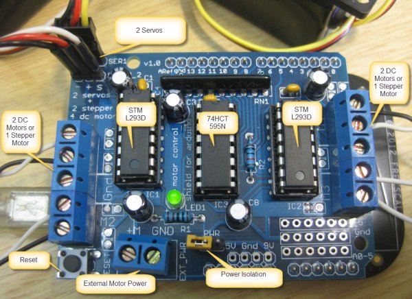
The board has two STMicroelectronics L293D Motor H-Bridge IC’s which can drive up to 4 DC motors (or up to 2 stepper motors) with 0.6 A per bridge (1.2 A peak). The 74HCT595N (my board has the SN74HC595 from Texas Instrument) is a shift register used for the H-Bridges to reduce the number of pins needed (more about this in a next post). A terminal block with jumper is providing power to the DC/stepper motor. The 5 VDC for the servos is taken from the FRDM board.
❗ The FRDM-KL25Z can only give a few hundred mA on the 5V Arduino header. That works for small servos, but I recommend to cut the 5V supply to the servos and use a dedicated 5V (or 6V) for the servos.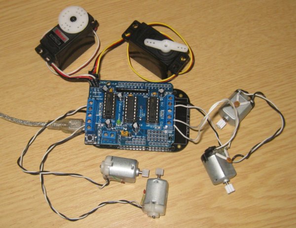
Outline
In this tutorial, I’m creating a project with CodeWarrior for MCU10.4 for the FRDM-KL25Z board, and then add support for two servo motors.
Processor Expert Components
This tutorial uses added Processor Expert components which are not part of CodeWarrior distribution. The following other components are used:
- Wait: allows waiting for a given time
- Servo: high level driver for hobby servp motors
Make sure you have the latest and greatest components loaded from GitHub. Instructions how to download and install the additional components can be found here.
Creating CodeWarrior Project
To create a new project in CodeWarrior:
- File > New > Bareboard Project, give a project name
- Specify the device to be used: MKL25Z128
- OpenSDA as connection
- I/O support can be set to ‘No I/O’
- Processor Expert as Rapid Application Development option
This creates the starting point for my project:
Servo Motor
Servo motors are used in RC (Radio Control) or (hobby) robotics.
The motor has 3 connectors:
- GND (Black)
- Power (Red), typically 5V, but can be 6V or even higher
- PWM (White or Yellow), signal for position information
The PWM signal typically has frequency of 50 Hz (20 ms), with a duty (high duration) between 1 ms and 2 ms.
The screenshot below shows such a 50 Hz Signal with 1.5 ms duty cycle (servo middle position):
Many servos go below 1 ms and beyond 2 ms. E.g. many Hitec servos have a range of 0.9…2.1 ms. Check the data sheet of your servos for details. If you do not have a data sheet, then you might just experiment with different values.
With a PWM duty of 1 ms to 2 ms within a 20 ms period, this means that only 10% of the whole PWM duty are used. This means if you have a PWM resolution of only 8bits, then only 10% of 256 steps could be used. As such, an 8bit PWM signal does not give me a fine tuned servo positioning.
The duration of the duty cycle (1..2 ms) is translated into a motor position. Typically the servo has a built-in closed-loop control with a microcontroller and a potentiometer.
💡 I have found that it is not important to have an *exact* 50 Hz PWM frequency. You need to experiment with your servo if it works as well with a lower or higher frequency, or with non-fixed frequency (e.g. if you do a software PWM). Many servos build an average of the duty cycle, so you might need to send several pulses until the servo reacts to a changed value.
Servo Processor Expert Component
I’m using here my own ‘Servo’ component which offers following capabilities:
- PWM configuration (duty and period)
- Min/Max and initialization values
- Methods to change the duty cycle
- Optional command line shell support: you can type in commands and control the servo. This is useful for testing or calibration.
- Optional ‘timed’ moving, so you can move the servo faster or slower to the new position in an interrupt driven way
💡 Of course it is possible to use servos without any special components.
From the Components view, I add the Servo component. To add it to my project, I can double-click on it or use the ‘+’ icon in that view:
In case the Processor Expert views are not shown, use the menu Processor Expert > Show Views
This will add a new ‘Servo’ component to the project:
But it shows errors as first the PWM and pin settings need to be configured. PWM Configuration
On the Arduino Motor/Stepper/Servo shield the two Servo motor headers are connected to PWM1B and PWM1A (see schematic):
Following the signals, this ends up at following pins on the KL25Z:
- Servo 1 => PWM1B => Arduino Header D10 => FRDM-KL25Z D10 => KL25Z pin 73 => PTD0/SPI0_PCS0/TPM0_CH0
- Servo 2 => PWM1A => Arduino Header D9 => FRDM-KL25Z D9 => KL25Z pin 78 => ADC0_SE6b/PTD5/SPI1_SCK/UART2_TX/TPM0_CH5
From the pin names on the Kinets (TPM0_CH0 and TPM0_CH5) I can see that this would be the same Timer (TPM0), but with different channel numbers (CH0 and CH5).
For my first servo Processor Expert has created for me a ‘TimerUnit_LDD’ which I will be able to share (later more on this). The TimerUnit_LDD implements the ‘Logical Device Driver’ for my PWM:
So I select the PWM component inside the Servo component and configure it for TPM0_C0V and the pin PTD0/SPI0_PCS0/TPM0_CH0 with low initial polarity. The period of 20 ms (50 Hz) and starting pulse with of 1.5 ms (mid-point) should already be pre-configured:
I recommend to give it a pin signal name (I used ‘Servo1′)
That I need to set the ‘initial polarity’ to low is a bug of Processor Expert in my view: the device supports an initial ‘high’ polarity, but somehow this is not implemented? What it means is that the polarity of the PWM signal is now inverted: a ‘high’ duty cycle will mean that the signal is low. We need to ‘revert’ the logic later in the Servo component.
Because of the inverted PWM logic, I need to set the ‘Inverted PWM’ attribute in the Servo component:
The other settings of the Servo component we can keep ‘as is’ for now. The ‘Min Pos PWM’ and ‘Max Pos PWM’ define the range of the PWM duty cycle which we will use later for the servo position.
For more detail: Tutorial: Arduino Motor/Stepper/Servo Shield – Part 1: Servos