This is a clock designed to keep accurate time (independent of atomic or GPS), display local sunrise, sunset and solar noon, and also adjust itself for daylight savings time.
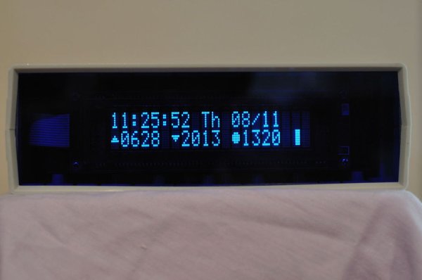
I wanted the clock to be easy to use and be flexible. The setting functions are menu-driven, you set each parameter one digit at a time (with live data validation) and you can abandon changes if you want. You can have 12 or 24-hour time. It uses a bright, legible VFD character display – you can choose even more readability with a 2×3 big-character mode.
Finally, VFDs are bright and readable, but sometimes you don’t want them lighting up the room. So, you can set a schedule of when the display is bright, dim or off. You can turn the display on or off any time you want, as well.
I hope to go over key elements of the software and hardware design to help you in building a clock just like this one or to give you ideas for anything that needs menus, data validation, timekeeping and so on.
Step 1: Design Choices
As stated in the intro, I wanted the clock to be easy to use, accurate, simple but also flexible.
Easy to use:
– menu-driven setting options
– digit-by-digit setting (who wants to go up or down to set something like longitude?)
– data validation to keep the user from inputting impossible time, date, location etc…
– buttons match the way it is used, eg. you want to look at it while setting, so the left button is really the right button
– most common functions on their own button, eg. display on/off, big/small digits, etc…
Accurate:
– must keep time accurately without using radio time; DS3231 RTC is accurate to 2 ppm/year or approximately +/- 1 minute per year
Simple:
– no buttons visible anywhere except the back
Flexible:
– allow adjustment of DST start and end
– allow 12/24 time
– support display brightness schedule
I suppose you can add to “Simple” that it uses the Arduino platform. There isn’t actually an Arduino board inside, though you could use one; I used a Modern Device RBBB Arduino clone and a Wicked Device RBBB shield board. I chose the RBBB because it’s cheap, flexible and sports a power jack, which I needed anyway and is a pain to do properly on protoboard. I chose the Wicked Device RBBB shield as it supports the RBBB and because it gave me sufficient protoboard space to mount a 2032 coin cell holder for the DS3231 backup power and have a header for the 14-pin cable to the VFD display.
Step 2: Hardware Choices
As mentioned before, I went with the Arduino platform – not so much for the Arduino-branded hardware but mostly because I’ve done a number of projects in it and because there’s plenty of hardware flexibility. I use pre-made boards where it will save me time and grief, especially where custom circuitry is involved. Some good examples are wiring up the power jack (few have the right spacing for 1 mm pitch protoboards) and wiring the resonator (though I show how to do this on a breadboard in my project “Arduino-Powered Four Letter Word Generator”).
One of the big reasons for going with the Wicked Device RBBB board was the 14-pin SO surface mount area. The DS3231 is a 16-pin SO part, but it turns out pins 8 & 9 are NC (not connected) so it was possible to shift the chip one leg to the right and mount it on the remaining 14 pads. Otherwise you have to buy and solder up a 16-pin SO to through-hole adapter, make your own PCB or buy something pre-made like a Chronodot. I needed some space to solder a 14-pin header for the VFD and the battery holder so the Wicked Device RBBB was the right choice. It was also the cheapest choice.
I chose the LCD-compatible VFD display because I wanted readability over all else. VFDs have some disadvantages, namely cost and power consumption. I got lucky and found an eBay seller with a lot of these at a good price. If I had to order directly at 1x quantity from Noritake I might reconsider. This project is wall-powered, so power consumption is not a problem. The VFD is a CU20029ECPB-W1J, if you’re wondering.
Because we have a power-hungry VFD (~300ma @ 5v) I decided against a linear power regulator. I have tried it before with this VFD and it just gets too hot for a non-vented enclosure, even with a 7.5v power supply. A good 5v regulated switch-mode power adapter is cheap, reliable and keeps your project cool inside. The RBBB provides for a linear regulator but it is a simple matter of jumpering pins 1 & 3 where the regulator would go.
Finally, the case choice was a matter of finding one with a faceplate big enough to accommodate the VFD. It turned out that 1/8″ plexiglass needed just a bit of sanding along the edges with coarse grit sandpaper to size it to fit the existing faceplate channel. The case is a Pro’s Kit 203-115A. I got it from Alltronics.
For more detail: Solar-Oriented, Arduino-Powered Clock