Many AA or AAA battery chargers charge batteries in pairs, but plenty of devices use 1 or 3 batteries, meaning that some of your batteries get overcharged and some get undercharged. NiCd and NiMH batteries also benefit from an occasional full discharge, which most normal battery chargers won’t do.
If you’re anything like me you’ll end up with a lot of rechargeable batteries, none of which end up being charged properly, and some of which turn out to be completely unusable. It’d be perfect if you had a low-power battery charger that you could leave on all the time, that would charge your batteries individually, automatically discharge them, and give you an idea of their real capacity. That’s what you’ll make in this tutorial!
Note: To make this nice and easy, the charger uses Espruino’s GPIO pins to directly charge and discharge the batteries. This means it can’t charge batteries very quickly (it can take days to charge and discharge them!). NiMH batteries benefit from an occasional fast charge/discharge, which this charger can’t provide without some extra components – so it’s not perfect, but it is easy to build and will make sure your batteries are always topped up.
Step 1: What You Need…
You just need:
- One Espruino Pico
- A long Breadboard
- A Nokia 5110 (PCD8544) LCD display
- Some patch wire (normal solid core wire is fine)
- 4x 100 Ohm resistors
- AA or AAA battery holders with pins (available from Rapid Electronics: AA or AAA)
Step 2: Wiring Up
- Place the breadboard with the `-` row of pins right at the bottom, and the `+` row right at the top.
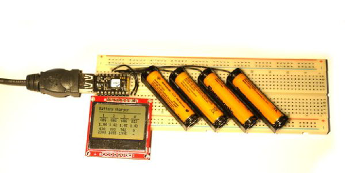
- Plug the Espruino Pico into the breadboard as far left as it will go (as in the picture)
- Add a wire from Espruino’s `GND` pin straight down to the bottom `-` row of pins
- Plug the LCD display into the breadboard below the Pico, with 2 pins sticking out to the right of the Pico (it should overlap the GND wire)
- Take a patch wire and connect from pin `B1` on the Pico to the top of a column 5 pins to the right of the Pico (see the picture)
- Fold a 75 Ohm resistor, cut it to length, and add it diagonally between the 5th column right of the Pico and the 6th.
- Now add 3 more sets of wires and resistors, from pins `A7`, `A6` and `A5`, to new columns, each with 7 columns of pins between it and the last. Note: This works for AAA batteries – for AA you will need to space the columns out a bit more.
- Cut the pins on your battery holders down so they’ll fit in the breadboard, and then place the battery holders in the breadboard at an angle: With the `+` contact relative to the resistor (as shown below), and with the `-` contact in the bottom `-` row of pins on the breadboard.
- Now add 2 wires for the LCD: `B10` to the pin nearest the Pico, and `B13` to the pin right on the edge.
Read more: Smart Battery Charger