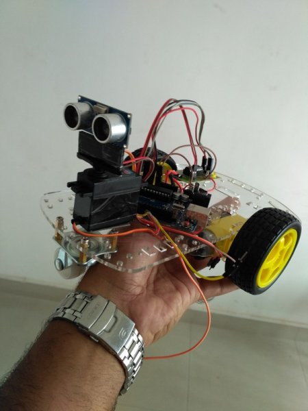
This project is designed to build a robot that automatically detects the obstacle on its path and guides itself whenever an obstacle comes ahead of it. This robotic vehicle is built, using Arduino UNO board. An ultrasonic sensor is used to detect any obstacle ahead of it. A motor driver IC and 2 DC motors are used for controlling the movement of the robot. A servo motor is also used in this project. The ultrasonic sensor is then mounted on the servo and by rotating the servo to different angles we will obtain the readings from the ultrasonic sensor in those angles. This will help the controller to detect the exact path to navigate. A Bluetooth module is also added to the project (which is optional ) in order to control the robot from your android phone when it is in manual mode.
Objectives of the Project
- Navigate safely by avoiding obstacles comes ahead.
- Detecting the exact path by checking the sensor readings in different angles.
- Send status of the robot movement (using Bluetooth module) to the nearby android phone when the robot is in automatic mode.
- Navigate in manual mode by receiving signals from the phone.
Let’s begin to build our project – Obstacle Avoidance Robot
Circuit Diagram
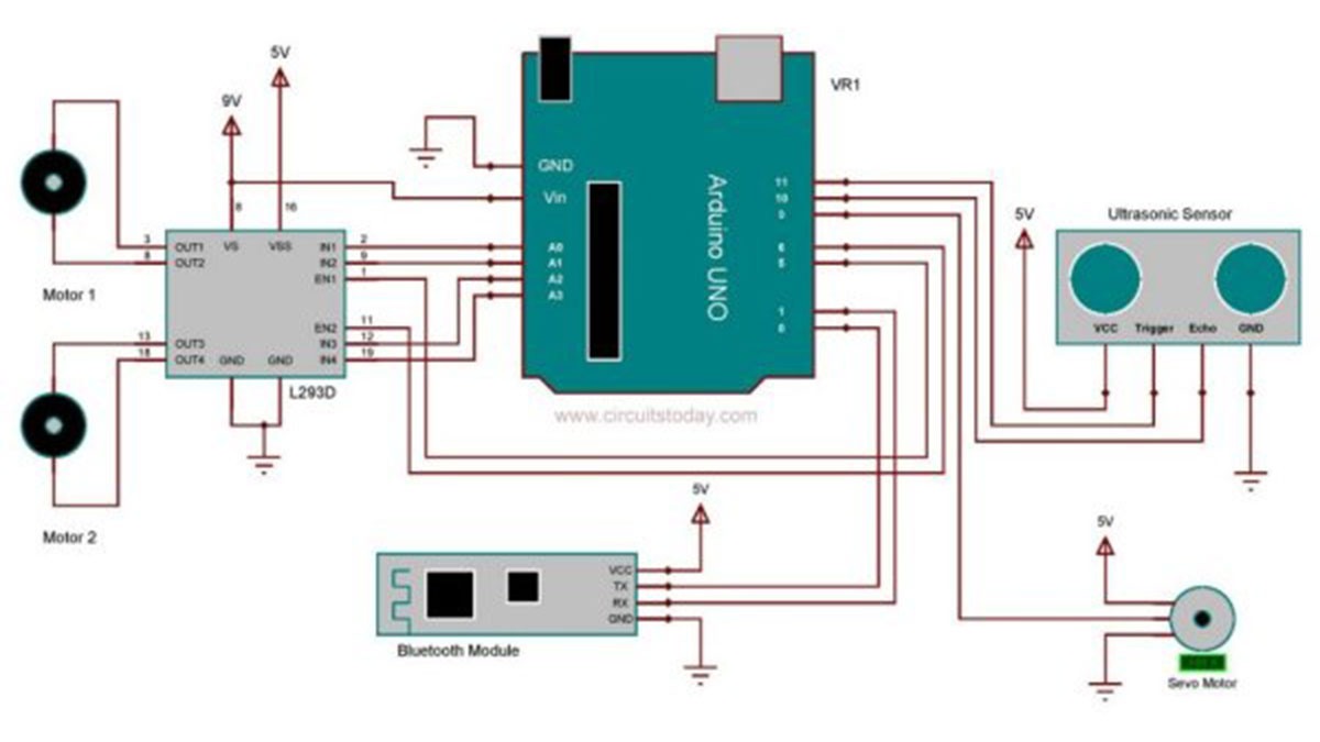
Assemble the circuit as shown in the diagram! Important connections are explained below.
HC SR04 is the ultrasonic sensor that we are using here. The ultrasonic sensor has 4 pins: Vcc, Trig, Echo and Gnd. Vcc and Gnd are connected to the supply pins of the Arduino. Trig is connected to the 11th pin and Echo is connected to 10th pin of the Arduino.
As mentioned earlier a motor driver IC called L293D is used for controlling the DC motors. It is a 16 pin IC which can drive two motors simultaneously. 1st and 9th pin are the enable pins, which are connected to the 5th and 6th pins of the Arduino board. Pins 2 and 7 are control inputs from microcontroller for first motor. They are connected to pins A0 and A1 of Arduino respectively. Similarly, pins 10 and 15 are control inputs from microcontroller for second motor. They are connected to pins A2 and A3 of Arduino.
When the robot is switched ON, both the motors of the robot will run and the robot moves forward. During this time, the ultrasonic sensor continuously calculate the distance between the robot and the obstacle in front of it. If the distance between the robot and the obstacle is less than 30cm, the robot will stop moving and rotate the sensor using servo motor to take readings in different angles. The correct turn which is to be taken can be decided by simply checking the angle in which sensor gives maximum reading. That will be the path with less obstacle. Servo motor have a signal line , which is connected to the 9th pin of arduino. The rotation of the servo is done by generating pwm signal on its signal line.
A Bluetooth module called HC05 is also used in this project (optional). It is connected to the RX and TX pins of Arduino. It is used here for controlling the robot with your android phone. We developed simple android app for this. The .apk file of the application is attached with this article. You can simply download and install it on your phone. By using the app , you can switch the robot to automatic or manual mode with a single click. And also shows the status of the robot when it is in automatic mode.
Read More: Robot using Arduino and Bluetooth Module (Obstacle Avoidance Robot)