
Summary of 4×1 WiFi Wireless Antenna Switch
The author, a physics student and ham radio operator, built a WiFi-controlled antenna switch to manage multiple bands (80m, 40m, 20m) from an attic without running extra cables. After rejecting bulky Raspberry Pi and expensive commercial solutions, they utilized the low-cost ESP8266 module combined with a standard relay design. The final project integrates these components onto a single PCB for a compact, wireless switching solution that avoids signal loss and high costs.
Parts used in the WiFi Wireless Antenna Switch:
- ESP8266 WiFi module
- Standard relay switch design
- Single PCB board
- Proper mounting box
I started playing with electronics back when I was 10 years old in Argentina, where I grew up. Then I got my ham radio operator license when I was 16 years old and I was very active in the ham club and on the air. It was then when I built my first vacuum tube transmitter and refurbished and old receiver (also vacuum tubes) that somebody from the club was throwing away. My interest for science and electronics grew and I ended studying physics but always tinkered with electronics, whenever I could.
I’ve moved a lot around the world for work (oil and gas) so my dedication to ham radio pretty much faded away. But it came back! Just recently, I got my ham radio operator license back and started to get active on 2mtr and on digital.
Due to lack of space outdoors, I had to settle for installing my center fed dipole on the attic (I have a long attic), but I quickly realized I needed more than 1 antenna. 80 mtr, 40 mtr, 20mtr….
And I didn’t want to run multiple lines to the attic, so an antenna switch was necessary.
I started playing with electronics back when I was 10 years old in Argentina, where I grew up. Then I got my ham radio operator license when I was 16 years old and I was very active in the ham club and on the air. It was then when I built my first vacuum tube transmitter and refurbished and old receiver (also vacuum tubes) that somebody from the club was throwing away. My interest for science and electronics grew and I ended studying physics but always tinkered with electronics, whenever I could.
I’ve moved a lot around the world for work (oil and gas) so my dedication to ham radio pretty much faded away. But it came back! Just recently, I got my ham radio operator license back and started to get active on 2mtr and on digital.
Due to lack of space outdoors, I had to settle for installing my center fed dipole on the attic (I have a long attic), but I quickly realized I needed more than 1 antenna. 80 mtr, 40 mtr, 20mtr….
And I didn’t want to run multiple lines to the attic, so an antenna switch was necessary.
ESP8266
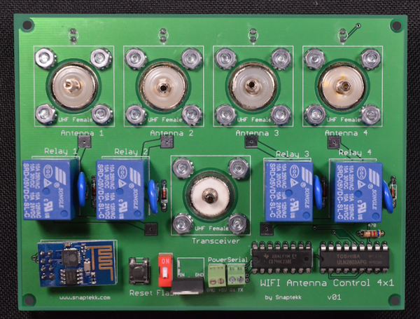
I bought a 4 position manual antenna switch and very quickly realized (again) that I did not want to go up and down the stairs with kids and wife sleeping to switch the antenna. And more importantly, I did not want to run another set of cables to drive a wired remote controlled one. Wireless was the solution. I checked the prices, and they were outside of my budget for a switch. So, what’s next? I came up with an idea. Get a RaspberryPi and add a relay board and then I have my WIFI wireless relay control. Add some UHF female SO-239s and we have a WIFI Antenna Switch. Well, two problems with this, first it is really clunky connecting all those coaxial cables to the relays and there would be a lot of signal loss (and good luck tuning that), its bulky and pretty difficult to assemble in one unit and that would not work properly; second, it was more expensive than I expected, even DIY it was around 100 dollars. I built it anyway and, well it worked for a while. But I was not happy so I looked around and came up with a better idea (or so I thought!). I found the ESP8266, a WIFI module which is small, cheap, I mean 3-dollars-cheap and fully programmable. Combining this module with a standard relay switch design, I thought I had a solution for way under 100.00 dollars integrated all in one single PCB board, suitable for mounting on a proper box. Lets look at the design.
For More Details: 4×1 WiFi Wireless Antenna Switch
- Why did the author build a custom antenna switch?
The author needed to control multiple antennas from different bands without running multiple coaxial lines to the attic or manually climbing stairs. - What problem occurred with the initial Raspberry Pi solution?
The Raspberry Pi setup was clunky, difficult to assemble, caused significant signal loss, and cost around 100 dollars even as a DIY project. - How does the ESP8266 improve the project compared to other options?
The ESP8266 is small, fully programmable, and costs only three dollars, allowing for an integrated single PCB design under 100 dollars. - What bands of operation are supported by this antenna switch?
The switch supports 80 meter, 40 meter, and 20 meter bands. - Why was a manual antenna switch rejected initially?
The author did not want to go up and down the stairs while their family was sleeping to change the antenna setting. - What type of connection method was chosen for the final design?
The final design uses a wireless WiFi connection controlled by the ESP8266 module.
