Summary of RGB LED Strip Circuit with Arduino
This Instructable guides users in building a circuit to PWM control a high-power RGB LED strip using an Arduino. It explains the need for transistors to handle current limits exceeding the microcontroller's 40mA capacity and details mounting components like transistors and voltage regulators onto heatsinks for thermal management. The project ensures safe operation of 9-12V LED strips by managing power distribution and heat dissipation effectively.
Parts used in the RGB LED Strip Circuit with Arduino:
- Microcontroller
- Breadboard or PCB
- RGB LED strip
- Battery (9-12v)
- 3 NPN transistors (TIP 120s)
- LM7805 Voltage regulator
- (4) 4-40 screws
- (4) 4-40 nuts
- (4) nylon washers
- 22g hookup wire
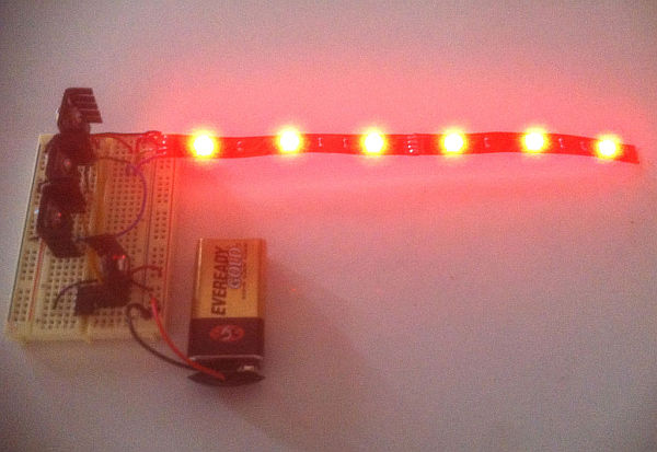
This Instructable covers the assembly of a circuit capable of PWM-ing (pulse width modulating) a high-power RGB LED strip and programming an Arduino to cycle through a range of colors. In this context, “high power” is 9-12 volts. I will discuss how to mount a transistor to a heatsink and assemble the circuit. I will not go into soldering as some of the RGB LED strip comes with leads (and there is no shortage of great tutorials out there). Also, I will use the most plain, non-jargony language possible to explain the circuit because I know how frustrating it can be to learn this stuff.
You will need:
– A Microcontroller
– Breadboard or PCB
– RGB LED strip
– Battery (9-12v)
– 3 NPN transistors (I’m using TIP 120s)
– LM7805 Voltage regulator (optional, but recommended)
– (4) 4-40 screws (length, up to you)
– (4) 4-40 nuts
– (4) nylon washers
– 22g hookup wire
Step 1: Brief Explanation of the Electronics
If you are new to Arduino and are wondering why more than a few LEDs or other components like motors won’t activate when functions are called in the code, its because each output has a current limit of 40mA. In other words, a component cannot draw more than 40mA of current from each channel. To refer to the water analogy of electronics, the “pump pressure” is 5V, and the amount of water is the number of electrons (measured in Amps, or in our case, a much smaller amount – milliamps, mA). To accommodate a load that requires more current than 40mA at 5V, we will use our microcontroller to control a transistor, which will provide a component with power from an external source (the battery).
Without getting too technical, its worth knowing that individual strips are made up of 3 LEDs in series which can be cut with clippers at any junction. If you want to cut the strip at any point, just be sure to leave connection points on each halve. To understand how the RGB LED strip can be powered with 9-12V, you need to know the difference between circuits in series vs. parallel (this page has a simple explanation with great illustrations, and there is a popular Instructable that covers wiring LEDs in series & parallel). Basically, when LED’s are connected in series, the supply voltages and necessary current are added together (respectively). For example, since an average RGB LED requires 3.3 V and 60mA (at full brightness; each color channel draws 20mA, so R-G-B all on at same time is 20 x 3 = 60mA), each strip of 3 RGB LEDs will require approximately 9.9V (the strip I’m using from Jameco can be powered between 9-12V. Be sure to look at your product’s datasheet to prevent frying your components. Not all RGB LED strip is powered in the 9-12V range, such as Adafruit’s digitally addressable RGB LED strip). One more thing, these strips are “common anode,” meaning the LEDs share a positive terminal (read about anode vs. cathode).
Perhaps the greatest take-away is the power limitation of the Arduino. The next section which shows how to use a transistor can be applied to all sorts of other components (ex. motors, solenoids, servos) that require more than 40mA at 5V.
Step 2: Mounting a Transistor to a Heat Sink
A heat sink‘s function is to dissipate heat so components don’t fry, melt connections/become un-soldered, or become too hot to touch. This is really important if you’re using a 7805 for voltage regulation, which I’m also doing in this circuit. The 7805 will output a steady 5V to the microcontroller and dissipate quite a bit of heat. I like to do this because I don’t trust the Arduino SMD voltage regulator, especially on ProMinis which I use frequently (even thought the Arduino Uno datasheet says the input voltage can be as high as 20V).

This part is pretty straight-forward. Apply some heat sink compound to the transistor (first image in this series) and then put the nylon washer on screw on then through the transistor (second). The compound increases thermal conductivity, which aids in the dissipation process. Lastly, fasten the nut to the back of the heat sink.
Repeat two times for each transistor and once for the 7805.
For more detail: RGB LED Strip Circuit with Arduino
- Why do some LEDs fail to activate with Arduino code?
Each output channel has a current limit of 40mA, so components requiring more current need an external power source controlled by a transistor. - How can I power an RGB LED strip that requires 9-12 volts?
You must use a transistor to allow the component to draw power from an external battery while the microcontroller controls it. - What is the recommended way to prevent overheating during assembly?
Apply heat sink compound to the transistor and mount it on a heatsink using nylon washers and screws to dissipate heat effectively. - Can I cut my RGB LED strip at any point?
You can cut the strip at junctions where three LEDs are in series, but you must ensure connection points remain on each half. - Does every RGB LED strip operate on 9-12 volts?
No, not all strips are powered in this range; for example, Adafruit's digitally addressable strips differ, so checking the datasheet is essential. - What is the function of the LM7805 voltage regulator in this project?
The 7805 outputs a steady 5V to the microcontroller and dissipates significant heat, which is why it should be mounted on a heatsink. - Is soldering required to assemble this circuit?
Soldering is not discussed as some RGB LED strips come with leads, though it may be necessary depending on the specific components used.