Summary of Maze Solving Robot
This article details the creation of a maze-solving robot capable of finding the exit using a left-hand-on-the-wall algorithm, then optimizing and retracing the shortest path without hitting dead ends. The builder explains the theory behind maze-solving and route optimization, the robot’s layered acrylic chassis design, motor and sensor installation, wiring, and the programming logic that processes sensor data and controls movement. The project uses Arduino for control and employs analog reflectance sensors for line detection, enabling the robot to follow and learn the maze path effectively.
Parts used in the Maze Solving Robot:
- 2 Micro Gear Motors
- Pair of Motor Brackets
- Pair of Wheels
- Ball Caster
- Analog Reflectance Sensor Array
- #2 Bolts and #2 Nuts
- Arduino RBBB
- Motor Driver IC
- 4AAA Battery Holder
- 4 Rechargeable AAA Batteries
- 3 1in Spacers (Home Depot)
- Hook up wire (22 gauge)
- Solder
- .100" Female and Male headers
- Velcro
In this guide, I will demonstrate how to construct a robot that can solve mazes. This is my third try at creating one. The initial attempt was a total flop. The second was proficient at reaching the maze’s end but could not backtrack and take the fastest route. This is my third and present one. It can reach the maze’s exit and, once placed back at the beginning, navigate the shortest route to the exit without entering any dead ends. I am surprised that it actually doesn’t make a mess.
This was just a short introduction, everything else from theory, building, and programming will be explained in later steps.
Parts list:
- 2 Micro Gear Motors
- Pair of Motor Brackets
- Pair of Wheels
- Ball Caster
- Analog Reflectance Sensor Array
- #2 Bolts and #2 Nuts
- Arduino RBBB
- Motor Driver IC
- 4AAA Battery Holder
- 4 Rechargeable AAA Batteries
General Parts:
- 3 1in Spacers (Home Depot)
- Bolts and nuts that fit the spacers (Home Depot)
- Hook up wire (I use 22 gauge)
- Solder
- .100″ Female and Male headers
- Velcro
Tools:
- Soldering Iron
- Philips Screw driver
- Wire Strippers
- Something to cut the wire with
Step 1: The Theory Part 1
How do you solve mazes?
There are essentially 2 stages. The initial step is to navigate through the maze and locate its conclusion. The next step is to enhance the route so that your robot can navigate the maze again flawlessly, avoiding all dead ends. How does the robot locate the maze’s endpoint?
I employ a method known as the left hand on the wall. Picture yourself in a labyrinth as you consistently trace your left hand along the wall. Accomplishing this task will eventually lead you to escape a maze without any loops. This guide will specifically focus on mazes that do not have any looping paths. This algorithm of placing the left hand on the wall can be simplified to these basic conditions:
– If you are able to make a left turn, feel free to do so.
– if you are able to keep driving in a straight line, then proceed straight ahead.
If you are able to make a right turn, then proceed with turning right.
– When faced with a dead end, simply reverse direction. This is a crucial decision-making process for the robot at intersections. An intersection is a point within the maze where you can choose to change direction. If the robot fails to turn when presented with the chance to turn, it is viewed as continuing in a straight path. Every action made at a junction or while changing direction must be remembered.
L = left turn
R= right turn
S= going straight past a turn
B= turning around
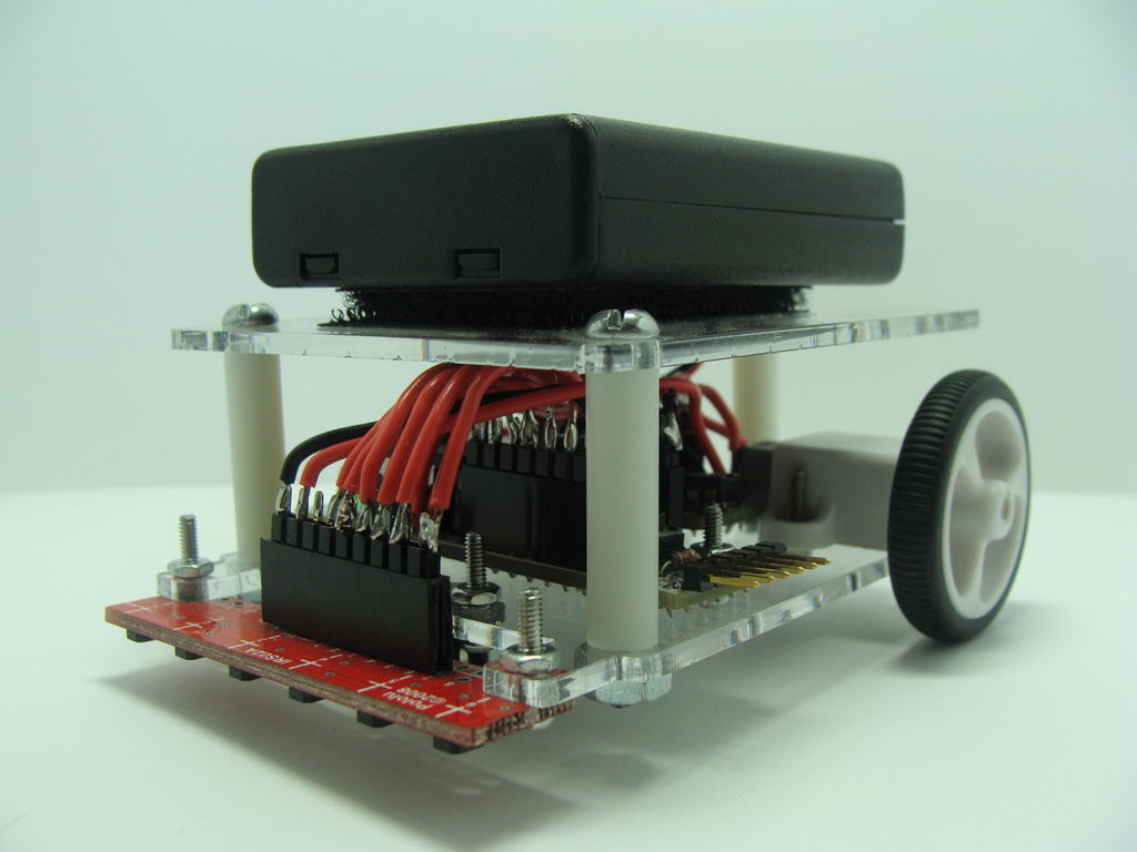
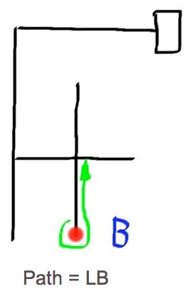
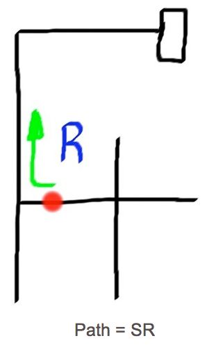
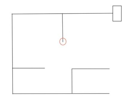
So let us apply this method to a simple maze and see if you can follow it. View the photos to see this method in action.
The red circle will be the robot.
As you can see in the photos for this example, the final path is LBLLBSR.
Step 2: The Theory Part 2
Alright, you now have a route. How does the robot convert “LBLLBSR” into the right path in this situation? Let’s examine the right course of action. Examine the pictures to find the right route.
The ultimate accurate route is SRR.
We need to change our direction from LBLLBSR to the correct path, which is SRR. We begin by examining our mistakes. A “B” shows the robot changed direction, signaling it took the incorrect route. In order to improve the route, we need to eliminate the “B” through substitution.
Step 3: The Theory Part 3
Let’s examine the initial 3 steps in the route “LBLLBSR”. These actions are known as “LBL”.
That movement appears similar to the picture. Instead of making two left turns and then turning around, the robot should have proceeded straight ahead. Therefore, it can be stated that LBL equals S. This replacement is utilized by the robot to enhance the route. This is just one instance, however, here is the complete roster: LBR.
= B
LBS = R
RBL = B
SBL = R
SBS = B
LBL = SYou may not come across all of these when maze solving, but they are required when optimizing the path. Some even put “B” back into the path. This is required to further optimize the path correctly. You can figure out why for yourself or just trust me.
Lets optimize our path now that we know how to:
Path = LBLLBSR
LBL = S so our new path would be: SLBSR
We also know LBS = R so our new path would be: SRR
As you can see we got the path that we were looking for.
My robot optimizes the path as it travels. The path is stored in an array and every time it goes to store a new move, it checks to see if the previous move was a “B”, if it was then it optimizes the path. You need to know at least 3 moves to optimize the path: The move before and after the turn around (and the turn around itself).
Step 4: The Theory Part 4
Here is another example.
Using the left hand on the wall algorithm, here is the path the robot would take:
LLLBLLLRBLLBSRSRS
Now here is the process of shortening that path:
LL(LBL = S)LL(RBL = B)(LBS = R)RSRS
The new path would be:
LLSLLBRRSRS
Continue shortening it until all the “B”s are gone:
LLSL(LBR = B)RSRS
The new path would be:
LLSLBRSRS
Continue shortening it:
LLS(LBR = B)SRS
The new path would be:
LLSBSRS
Continue shortening it:
LL(SBS = B)RS
The new path would be:
LLBRS
Continue shortening it:
L(LBR = B)S
The new path would be:
LBS
The final path is:
LBS = R
Step 5: The Design
I want to clarify that your robot doesn’t need to be constructed in the same way as mine. The main thing I notice is that I created and used a laser cutting machine to make a frame for my robot. I’ll upload the AutoCAD file, but that’s pretty much all I can handle. If you cannot laser cut the design, there is no need to fret. If you have an Arduino, identical sensors, and motors, you can make my code function on your robot with minimal modifications. Lately, I assisted someone online who replicated my design but did not include laser-cut components. The code operated on his robot with minimal adjustment.
You can observe in the pictures the design I created and the components I utilized a laser cutter to produce. The components are created using acrylic material measuring .08 inches in thickness. This is available for purchase at The Home Depot.
The third photo displays the lower level in my two-tier chassis plan. The lower level features mounting holes at the back for attaching motors, at the front for attaching the ball caster, a hole for the Arduino, and 2 tabs at the front for the sensor. The lower deck also includes 3 mounting holes for attachment to the upper deck with bolts and spacers.
The upper deck features a sole, spacious opening for routing wires from the battery pack, which is secured with velcro on top, to the electronics located on the lower deck. It has three openings which enable connection to the lower platform as well.
It is a straightforward, space-saving design that enables easy assembly with minimal wiring.
You will see in the next steps how and where the parts fit on.
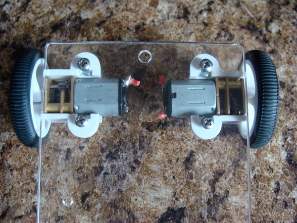
Step 6: Attaching The Motors
Step 7: The Arduino
The initial step you need to take is to adhere to the guidelines for putting together your RBBB. The instructions can be found right here. You should trim a section of the board as indicated in the bottom of the instructions, since it will not be necessary. If you don’t require the power jack or regulator, simply cut them off. Using a big pair of tin snips is the most simple method to cut the board, although hack saws, jewelers saws, and band saws are also effective options. Avoid soldering any headers onto the board except for the ones required for the FTDI programming port.
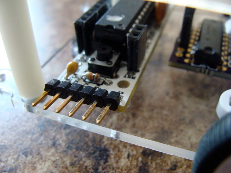
Then, attach a 9 pin row of female headers to the board’s left side, going from pins marked “5v” to “A0”. This will connect with the sensor plug at a later time. Attach a 4 pin row of female headers on the board’s right side from pins marked “D5” to “D8”. These pins are going to be utilized for managing the motor controller. In the end, attach a two-pin row of female headers to the right side of the board, specifically on the GND and 5V pins. These will provide electricity to the motor controller.
You have the option to disregard the motor controller and top deck shown in the photos. We will address those later.
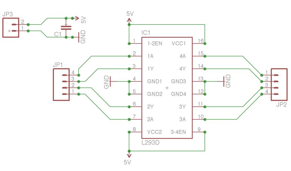
Step 8: The Motor Controller
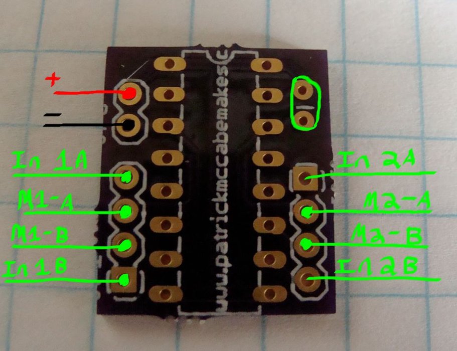
The initial step you need to take is to adhere to the guidelines for putting together your RBBB. The instructions can be found right here. You should trim a section of the board as indicated in the bottom of the instructions, since it will not be necessary. If you don’t require the power jack or regulator, simply cut them off. Using a big pair of tin snips is the most simple method to cut the board, although hack saws, jewelers saws, and band saws are also effective options. Avoid soldering any headers onto the board except for the ones required for the FTDI programming port.
Then, attach a 9 pin row of female headers to the board’s left side, going from pins marked “5v” to “A0”. This will connect with the sensor plug at a later time. Attach a 4 pin row of female headers on the board’s right side from pins marked “D5” to “D8”. These pins are going to be utilized for managing the motor controller. In the end, attach a two-pin row of female headers to the right side of the board, specifically on the GND and 5V pins. These will provide electricity to the motor controller.
You have the option to disregard the motor controller and top deck shown in the photos. We will address those later.
As you can see I also went ahead and used some of the #2 nuts and bolts to bolt down the ball caster and Arduino.
Step 9: The Sensor
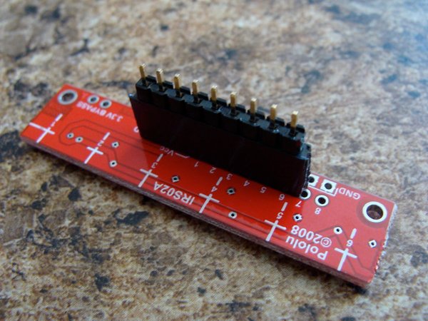
The sensor is provided in a grouping of 8 sensors. There are two things at the end that can and should be taken out. I utilized a set of diagonal cutters to accomplish this task. Solder a 9-pin female header strip onto the sensor, connecting from the “GND” to pin “6” of the sensor. Next, I inserted a row of male pins into the socket.
These sensors emit an analog voltage depending on the amount of reflected IR light. These can be utilized to spot the black and white regions on the maze. If a white surface is detected by the sensor, it will output a low voltage close to 0V. If a dark surface is detected, the sensor will produce a voltage close to VIN.
Step 10: Attach the Top Deck
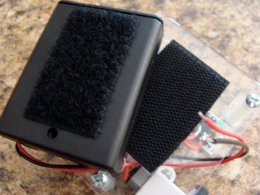
Secure the upper deck with 1 inch spacers, bolts, and nuts. Use Velcro to fasten the battery pack onto the top deck. Thread the cords from the battery pack through the opening in the upper platform to the lower platform. This battery pack comes with an integrated power switch already.
I discovered that not putting the screw in the battery pack was the simplest option. The screw stops the battery pack from opening, but it also has clips that effectively keep it closed even without the screw. This enables a convenient battery replacement by simply sliding open the battery pack. This implies you don’t have to remove the battery pack from the Velcro in order to replace the batteries.
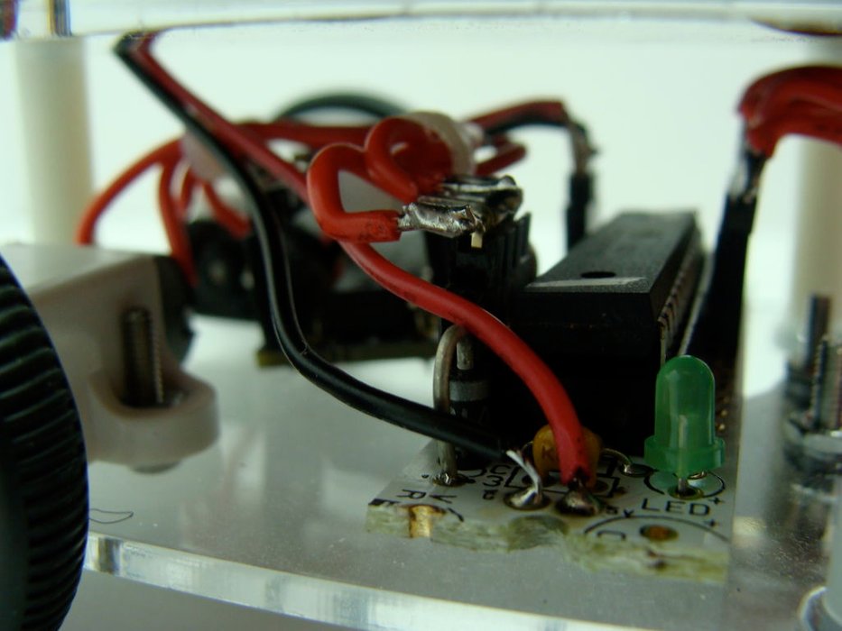
Step 11: Attach and Wire the Sensor
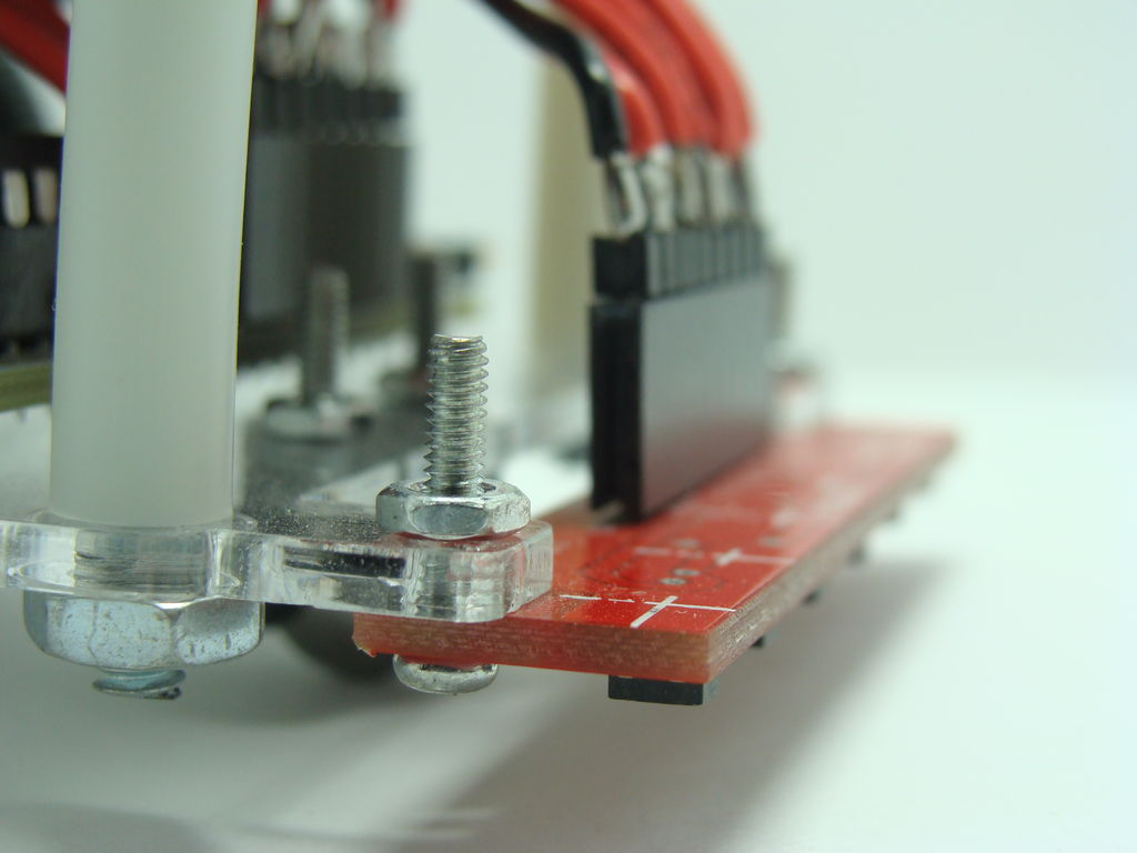
Step 12: Attach Power
Step 13: The Program
Writing this program was a fun experience for me. Essentially, there are several functions that handle the entire process of solving the maze. The function on the wall’s left side is responsible for processing the sensor data and guiding through the maze based on the predefined rules. The turning operations are set up so that the robot keeps turning until it detects the black line, at which point it moves forward. Additionally, there is a feature that has been programmed to include limited line-following abilities. While it’s not a PID line following method, it does enable the robot to remain on track. This function is in charge of regulating the speed of the robot.
The more specific purpose is to shorten the route. At each intersection, there is a letter indicating the robot’s chosen direction. If the letter before was “B” – showing a mistake – the function that reduces the path is executed to replace letters for those 3 letter combinations mentioned before.
At last, there is a feature that enables the robot to retrace the shortest route it determined, once it is lifted up and placed back onto the black line. The robot is able to determine when it has been placed back down and will then follow the shortest path that has been calculated.