Summary of Interfacing Electronic Circuits to Arduinos
Summary: This tutorial explains interfacing an Arduino (preferably Mega) with an ARINC 429 transceiver (DEI1016). It covers ARINC 429 basics, choosing parts, reading the chip data sheet, interpreting timing diagrams, reset/initialization and read sequences, and translating timing requirements into Arduino code. The author chose receiver-only use, a 1 MHz clock, and verifies pin and timing requirements before coding.
Parts used in the Arinc429eReader:
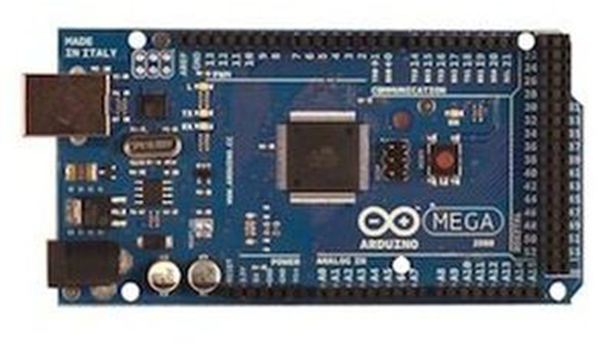
- Arduino Mega
- DEI1016 ARINC 429 transceiver (40-pin DIP)
- 1 MHz clock source (1 MHz clock chip or equivalent)
- Power supply providing 5 V
- Wiring/16-pin data bus connections
- Ground connection
- Optional: ARINC 429 receivers (on DEI1016)
- Optional: Logic level control lines (MR, LDCW, SEL, OE1, DR1, etc.)
Interfacing Electronic Circuits to Arduino
In this tutorial, I show how to link an Arduino to an ARINC 429 transceiver as an illustration of interfacing an Arduino with circuits, so you can use these methods for your projects.
The ARINC 429 bus is commonly utilized for computer to computer communications on aircraft. The ARINC 429 bus operates at either a slow speed of 12.5 kbps or a fast speed of 100 kbps. The bus operates using two wires (in addition to a ground). Each data item is sent in a 32-bit word for transmission. Normally, the first 8 bits, referred to as the label, are used to identify the information contained in the ARINC word. Bits 9 and 10 often dictate the Source/Destination Indicator, but they can also contain data or serve as an extension of the label. Information can be located between bits 11 and 29 and could be in the form of binary twos complement, binary coded decimal, or a set of individual bits. Bits 30 and 31 contain the Sign Status Matrix, indicating Normal operation, Failure Warn, No Computed Data, and Functional Test. The final position in the 32-bit word is reserved for the Parity bit, set to guarantee the word maintains an ODD parity.
Avionics equipment manufacturers, aircraft manufacturers, and avionics equipment service centers possess specialized testing tools for retrieving data from ARINC 429 data buses. I have aimed to own and use my own testing tools, which inspired me to develop the Arinc429eReader. While it can function as a standalone tutorial, I think the target audience for this device is restricted. I am going to share a more comprehensive guide on establishing connections between an Arduino and various electronic circuits.
Step 1: Deciding to Do the Project
Step 1a: Solved Already?
Before attempting to address your issue, make sure to verify if it has already been resolved by another individual. Utilize Google to search for information.
I found several companies in my research that manufacture ARINC 429 to USB converters, but they typically cost $1500 US dollars or more. A more efficient solution was necessary. I found an affordable ARINC 429 transceiver in a 40 pin DIP package. I reached out to the company and they provided me with free samples. Despite having a transmitter and two receivers, I only needed the receivers at the moment, making this chip a good choice.
Step 1b: Can I do it?
The task ahead is to determine if you have the skills (and the motivation) needed to finish the project. I acquired and examined the ARINC 429 transceiver chips’ specifications to reach a decision.
In my observation of the sample, I found that the chip operates on just 5v of power and does not need any unusual analog signals.
It also requires a 1 MHz clock to coordinate its operations. I thought about using either the Arduino’s clock or a 1 MHz clock chip.
Besides requiring a 16-pin data bus, it also necessitates 11 input/output signals. The amount of pins is too high for the Arduino UNO but appropriate for the Arduino Mega.
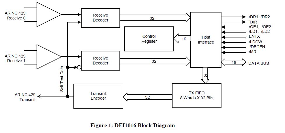
Please see the provided Figure 1.
What about software-related skills? I am well-experienced in coding for different processors and I utilize existing library code as models for tackling comparable issues. Arduino’s open-source code is perfect for my needs in this scenario.
Step 1c: Should I do it?
The task ahead requires determining if the project should be finished. Both money and time will be necessary. I usually prefer trying out new things solely for the purpose of gaining new experiences. It is generally not recommended to inquire about others’ opinions. Remember that numerous significant individuals in the past faced criticism from their contemporaries for their beliefs and behaviors.
I am confident that you are ready, enthusiastic, and able to move forward with your project! We should begin at this moment!
Step 2: Read the Chip Data Sheet
Step 2: Read the Chip Data Sheet
Get the chip data sheet for your chip and read all of it.
In my case the chip I found is the DEI1016 and its specification can be found here:
www.deiaz.com/data-sheets/DS-MW-01016-01-E.pdf
See the PDF file attached.
Let’s take a look at the timing diagrams. They can be intimidating at first but I am sure you can learn how to read them if you don’t know already.
Here is the timing diagram for the Reset and Initialization Sequence. I’ve added a few annotations to help you learn how to read the timing diagrams:
See timing diagram with annotations attached.
When the line is high, that means it is at 5 volts, and when low, it is ground, just like the Arduino’s digitalWrite HIGH and LOW.
Now let’s add in the values for all those time measurements in the timing diagram:
See timing diagram with times attached.
The time between the MR pin going HIGH and the LDCW pin going low isn’t specified, so let’s assume it isn’t critical.
Now let’s translate this into words:
Set MR LOW and hold it there for at least 200 ns.
Set MR HIGH.
Set LDCW LOW.
Set the data bus to its correct values and hold them there for at least 110 ns.
Set LDCW HIGH.
Let’s do the same thing for the Read operation:
See Figure 8 attached.
I find it intriguing how they decided to show the relative timings… OE1 should go LOW 0 ns after DR1 goes LOW, but 20 ns after SEL goes LOW.
Additionally, it seems that there is no specified time frame for when Word 2 will be considered valid. I believe the main point is that Tdoedr of 200 ns represents the duration for Word 2 to become valid, not the timing for raising OE1 to HIGH. I will test this reasoning to confirm if my assumptions are accurate.
Let’s translate this into words:
The DEI1016 chip sets DR1 LOW to indicate data has been received on Receiver 1.
Set SEL to LOW and wait for 20 ns.
Set OE1 to LOW.
Wait 200 ns for the chip to set the data pins. Read the data pins.
Set OE1 to HIGH and wait for 20 ns.
Set SEL to HIGH and wait for 30 ns.
Set OE1 to LOW.
Wait 200 ns for the chip to set the data pins. Read the data pins.
Set OE1 to HIGH.
Now that we have some understanding of how the pins need to be set to initialize the chip and to receive data, let’s turn these routines into Code.
 DS-MW-01016-01-E.pdf441 KB
For more detail: Interfacing Electronic Circuits to Arduinos
- What is the recommended Arduino for this project?
The Arduino Mega is recommended because the DEI1016 requires a 16-pin data bus and many I/O lines not available on an Arduino UNO. - What ARINC 429 transceiver was used?
The DEI1016 ARINC 429 transceiver in a 40-pin DIP package was used. - What voltage does the DEI1016 operate on?
The chip operates on 5 V power. - What clock frequency does the transceiver need?
The DEI1016 requires a 1 MHz clock to coordinate its operations. - How many data bus lines does the chip use?
The chip uses a 16-pin data bus. - What parity is used for ARINC 429 words?
Each 32-bit ARINC 429 word uses odd parity for the parity bit. - What are the basic steps for reset and initialization?
Set MR LOW for at least 200 ns, set MR HIGH, set LDCW LOW, set data bus values and hold for at least 110 ns, then set LDCW HIGH. - What is the read sequence for Receiver 1 on the DEI1016?
When DR1 goes LOW, set SEL LOW and wait 20 ns, set OE1 LOW, wait 200 ns, read data pins, set OE1 HIGH and wait 20 ns, set SEL HIGH and wait 30 ns, then perform OE1 LOW/200 ns/read again if reading Word 2.