Today we are going to make a real time clock Arduino shield. Doing so will give you a simple way of adding … real time capability to your projects such as time, date, alarms and so on. We will use the inexpensive Maxim DS1307 real-time clock IC.
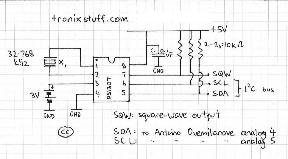
First of all, we need create our circuit diagram. Thankfully the Maxim DS1307 data sheet [pdf]has this basics laid out on page one. From examining a DS1307 board used in the past, the pull-up resistors used were 10k ohm metal films, so I’m sticking with that value. The crystal to use is 32.768 kHz, and thankfully Maxim have written about that as well in their application notes [pdf], even specifying which model to use. Phew!
So here is the circuit diagram we will follow (click on it to enlarge):
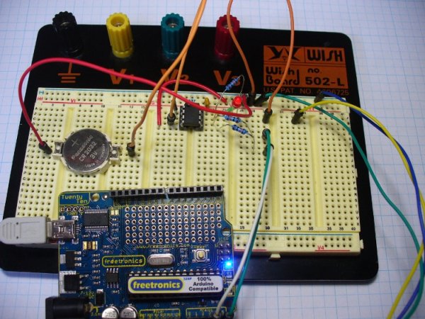
And here are our parts, ready for action:
The first thing to do is create the circuit on a solderless breadboard. It is much easier to troubleshoot possible issues before soldering the circuit together. Here is the messy test:
Messy or not, it worked. You can use the following sketch to test the circuit is working.
The next step is to consider the component placement and wiring for the protoshield. Please note that my board will most likely be different to yours, so please follow the schematic and not my board positioning. Try not to rush this step, and triple-check your layout against the schematic. As my protoshield has a green and red LED as well, I have wired the square-wave output to the green LED. You can never have too many blinking lights…
At this point I celebrated the union of tea and a biscuit. After returning to the desk, I checked the layout once more, and planned the solder bridges. All set – it was time to solder up. If you have the battery in the holder for some reason, you should remove it now, as they do not like getting warm. Furthermore, that crystal is very fragile, so please solder it in quickly.
And here we are – all soldering done except for the header sockets. At this point I used the continuity function of the multimeter to check the solder joints and make sure nothing was wrong with the circuit.
- One arduino protoshield pack. I like the yellow ones from Freetronics
- X1 – 32.768 kHz crystal – Citizen America part CFS206. You should probably order a few of these, I broke my first one very quickly…
- IC1 – Maxim DS1307 real time clock IC
- 8-pin IC socket
- CR2032 3v battery
- CR2032 PCB mount socket
- R1~R3 – 10k ohm metal film resistors
- C1 – 0.1 uF ceramic capacitor
For more detail: An Arduino real time clock shield