Summary of DIY AM Radio With Arduino
The article describes a DIY AM receiver project integrated with an Arduino, using a Software Defined Radio (SDR) approach to simplify RF circuitry. Key components include an optional RF amplifier based on the NE592 for signal boosting and high-pass filtering, a heterodyne frequency synthesizer using a 74HC4046 PLL/ Frequency Lock Loop controlled by Arduino for generating the local oscillator signal, a synchronous detector for demodulation, and filters. The design prioritizes low cost and ease of interface, with challenges in frequency accuracy addressed by adjusting reference frequency settings.
Parts used in the DIY AM Radio with Arduino:
- Arduino microcontroller
- NE592 RF amplifier IC
- 74HC4046 Phase Locked Loop (PLL) IC
- 74HC74 Dual D Flip-Flop IC
- Capacitors (22 nF, 560 pF)
- Resistors (including 1 kOhm and 40 Ohm equivalents)
- Jumpers (for gain selection)
- Passive components for filters (unspecified)
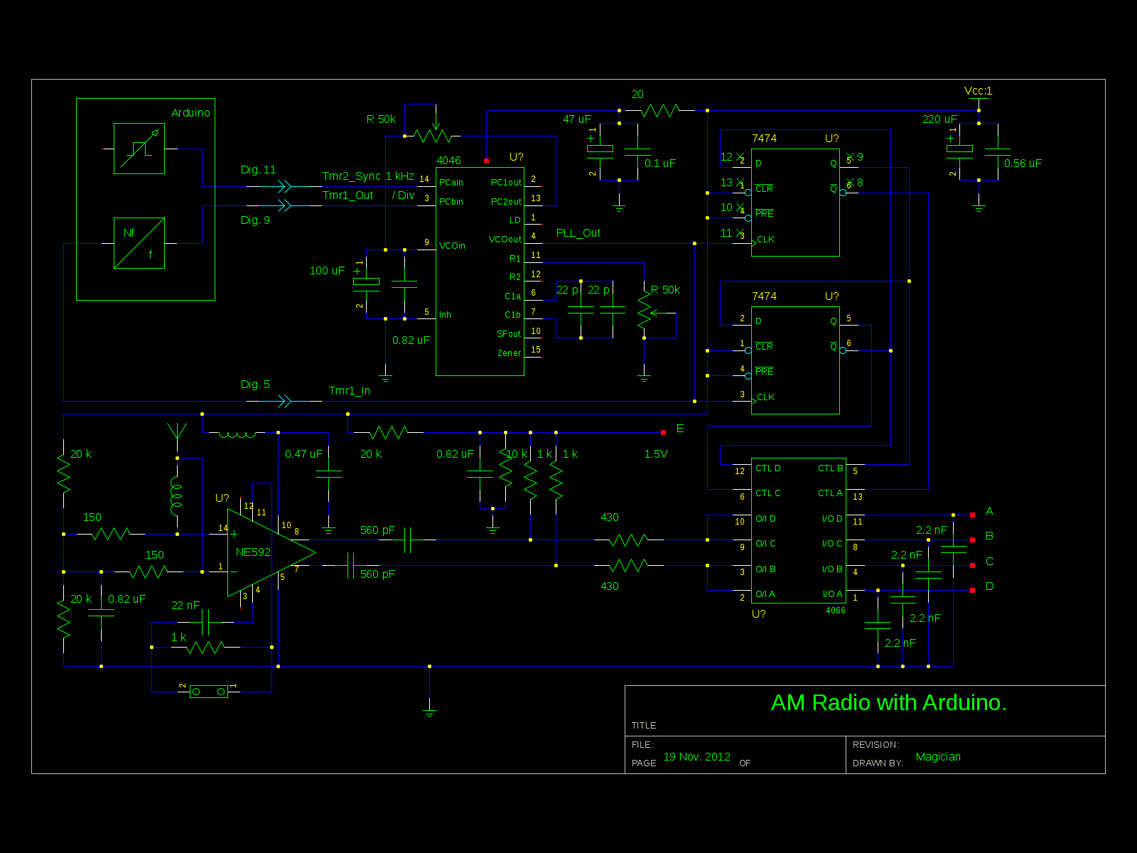
After I finished my last project, I couldn’t stop thinking how to build an AM receiver, that would also operate in conjunction with my little friend Arduino. To minimize a workload and complexity, especially with RF part of the circuitry, I come up to conclusion, that SDR (Software Defined Radio) is the best choice for hobbyist level project. There are 4 major functional parts so far ( work in progress! ):
- RF amplifier.
- PLL Frequency Synthesizer / Heterodyne.
- Synchronous detector.
- Filters.
RF amplifier is not strictly necessary, and can be omitted if receiving signal is strong enough. The same time it costs <1 $, doesn’t require any tuning (one jumper to select high / low gain) and plus it serves as HPF filter. You can see it on the left lower side, NE592 in basic configuration. With single power line +5V it’s running a little bit below minimum +/- 3V, and as gain almost linearly proportional to supply voltage it’s expected to be around 180 – 200. Gain drops to approximately 5 – 10 when jumper is open. There are two HPF around NE592. One is constructed with 22 nF capacitor between pins 11 and 4, has corner frequency 280 kHz ( 1 / 2 * pi * t, where t – time constant RC, with R = 40 Ohm internal resistance). When gain is switched to low position (open jumper sets 1 kOhm resistor in series) cut-off frequency drops to just 7.8 kHz. Second HPF is formed by 560 pF capacitors and 1 kOhm loading resistors at the amplifier outputs.
Next, the main part – Heterodyne. In order to keep overall cost of the project as low as possible, I was avoiding “out of the box” ( and enormously overpriced DDS / DAC Synthesizer, when IC alone costs ~20$ ). This is why I select 74HC4046. Cheap, very easy to interface with Arduino, and it requires only a few passive components. Well, there is some weak sides, in jitter and low overall stability, but it’s not an issue for low budget AM receiver design. At this point, I didn’t decide if SSB reception would be implemented. Two channels I and Q of the Synchronous Amplitude Detector (SAD) assembled, but there is no appropriate filter to do SSB decoding yet.
The primary function of the heterodyne oscillator is to supply 4x frequency to synchronous detector. 4x compare to receiving signal. To cover LW and MW bands, frequency of the oscillator has to go up to 1.7 MHz x 4 = 6.8 MHz. As you can see on the drawings above, 74HC4046 is configured as PLL frequency multiplier. Both parameters, reference frequency at pin 14 and multiplication coefficient are defined by Arduino (left upper side). So, if you need a frequency synthesizer up to 8 MHz for less than 1$, you can just “copy / paste” this part into your project ! Synthesizer can operate up to 32 MHz, if Arduino would count pulses not at pin 4 (VCO output), but after 74HC74 (two D-triggers, division by 4). One more things to mention, when I “cut-in” Arduino as programmable divider between pin 4 and pin 3, I cut a “phase” from the loop, and strictly speaking, it’s not PLL anymore, but rather Frequency Lock Loop (FLL).
In my initial pre-calculation, I define a reference frequency ( generated via Arduino Timer-2, pin 11 ) at 1 kHz, in order to satisfy both 9 and 10 kHz spacing in AM broadcasting in different parts of the world. It should works in SW band, where channel spacing is just 5 kHz. But it turns out, that my Arduino has an error in on-board crystal frequency ~0.2 %, so I can only get 998 or 1002 Hz. After multiplication, for example, to receive a local radio on 690 kHz wave I have to multiply by coefficient 690, error grows to unacceptable 345 Hz, (Arduino counts 4x frequency: 2 Hz x 690 / 4 = 345) allowing setting at 689.655 or 690.345. And there is no way to trim Arduino oscillator. The only choice (except using external precise clock) is to bring reference frequency down. Limit on the other end, is 16-bit multiplication coefficient. With 6.8 MHz heterodyne clock divided by 65535 value the reference can’t be lower than 103.76 Hz. It would be possible to “cascade” Timer-1 and Timer-0 in order to obtain 24-bits coefficient, but I can’t go so far. Even with multiplication by 16-bit value, PLL – FLL already gets too “tight”, as there is only one “synchronization event” per 65535 periods, which is too much for a simple 74HC4046. The compromise decision – selecting 244 Hz as a reference frequency, with highest multiplication coefficient 6.8 MHz / 244 = 27 882. 244 Hz comes from 16 MHz primary clock, divided by 256 preselector and 256 – max value I can set in 8-bit Timer-2. After 244 divided by 4 (74HC74, I mention earlier) the biggest frequency error in setting to radio station wave is reduced to 60 Hz, or just +/- 30 Hz.
To wrap up on PLL section, I’d insert timer_init subfunction here:
Source : DIY AM Radio with Arduino