The Problem
It is late night, and your cellphone rings. You can’t see where it is, you blindly grope around your nightstand, trying in vain to find that illusive switch that will illuminate your side of the bed. You clumsily turn on the lamp, locate your cellphone…and you miss the call. Damn. If only your light was easier to turn on.
The solution
What if all you had to do to turn on your lamp…was to touch anywhere metal on your bedside table? That sounds complicated though, and I AM a strong believer in keeping things simple whenever possible. I wonder if there are any open-source solutions that would allow such a thing to happen? Enter ARDUINO. A cheap, easy to use micro-controller that is dead simple to program and implement. This sounds like it might just work!
Since I am inherently thrifty (an HVAC-R apprentice, AND a Mennonite) I don’t want to commit my only $35 arduino board to the project. This means i’ll have to build my own Arduino, which will save me some money. Additionally, I’m only using a couple of pins, and not doing any serial communications, so I really don’t want to bother using an external oscillator. That means I’ll have to figure out how to enable the internal oscillator on an atmega 168.
Scope
This ‘ible will show you how to do the following (without a lot of hand-holding);
How to burn a bootloader to a standalone atmega168 using an Arduino UNO SMD edition.
How to enable the internal oscillator, so you can save $0.50 and not use a crystal.
How to program a standalone chip using an Arduino board and the Arduino IDE.
How capacitive touch objects work.
What is NOT covered
How to read a schematic diagram
How to solder
How to layout a protoboard
Since there are literally hundred of guides on how to solder, how to use schematic diagrams, and basics of digital electronics…I’m not going to go there. You’ll notice that there is a search bar in the upper right hand corner of this wonderful site. I’m sure if you try using it, you’ll find what you need. That said, if you are having troubles implementing THIS particular project, and it doesn’t involve such things as “How do I solder a resistor” then please feel free to ask.
***WARNING***
I am curmudgeonly, so my responses to questions that are not included in the scope of this ‘ible may or may not include some lighthearted mocking. You have been warned.
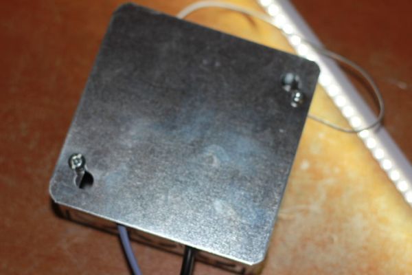
This is a proof of concept i’d put together before building the standalone.
Step 2: Burn the bootloader
he first thing we are going to need to do is upload the Arduino bootloader to our Atmega168 chip. Since I don’t want to use an external crystal, we are going to have to be sneaky. The only Arduino board that uses the internal crystal is the Lilypad. Thus, we are going to upload the LILYPAD bootloader into the Atmega168. There is a downside to this, in that the Lilypad bootloader takes about 10 seconds to initialize on power.
Depending on where you get your atmega168’s from, they may or may not have the internal crystal enabled. When programming an atmega168 for the first time, you’ll often need to provide the crystal before you can turn on the internal one. The crystal being used on the breadboard will not actually be included in the final project assembly.
In this step, we are going to program an arduino board to act like an ISP (In System Programmer). This will allow us to upload programs into a standalone atmega168 chip without having to purchase a dedicated ISP (I’m cheap, remember?).
1) Open the Arduino IDE software, and click on File>Examples>ArduinoISP.
2) Connect your arduino board to the computer, and click on “Upload”
3) Disconnect your arduino board.
4) Carefully insert your atmega168 chip into a solderless breadboard and connect it like the picture shows. Pin 1(RESET) has the DOT right next to it. Pin 1, in the diagram below is on the bottom left hand side of the Atmega168 chip. Before plugging the usb cord into your arduino, please double check that you haven’t attached +5VDC to the GND pin and the GND to the +5VDC pin on your standalone chip. If you do this, you’ll most likely let the smoke out of the chip. I speak from experience when I say it is very difficult to get the smoke back inside 😉
5) In the arduino IDE software, click on tools>Programmer>Arduino as ISP. (This tells the arduino IDE that you are going to be transmitting data from the arduino to an external chip.)
6) Now we need to select the bootloader for the standalone chip. Click tools>Board>LilyPad Arduino w/ Atmega 168. This bootloader will enable the internal oscillator, thus allowing us to forgo the external one in our project.
**THIS PROBABLY WILL NOT WORK IF YOU DO NOT HAVE A CRYSTAL ATTACHED DURING THE BOOTLOADER UPLOAD PROCESS**
7) Time to burn the bootloader! Click on tools> Burn Bootloader. The TX and RX lights on the arduino board should be flickering on and off, just like the video shows.
IF the arduino IDE gives you an error code that mentions ‘not in synch’, check your breadboard connections. There is probably a loose wire somewhere.
– An LED Strip
– Either a mosfet and transistor that your arduino can switch or a small DC Solid State Relay (SSR)
– Atmega168 DIP
– (1) 10k resistor
– (1) 1M resistor
– (1) 16 mHz crystal (might not be required)
– (1) solderless breadboard
– (1) protoboard/strip board.
– Wire
– Wire Nuts
– Wire Strippers, screwdrivers.
– Nuts and bolts
– Small electrical junction box
– (1) power supply that can supply both 12V and 5V. (Or 12V only, and use an 1805IC with a couple of capacitors to smooth it out)
The total cost on the project was about $20-$30. The most expensive part of the project was the electrical junction box and lid, which came to about $6.00. Home Despot is such a rip-off.
I troll ebay looking for electrical componenet from Thailand. There are some vendors that offer free shipping on a lot of stuff. The SSR I am using was $3 with free shipping. Same goes with the protoboard, get it for cheap on ebay.
The total cost on the project was about $20-$30.
For more detail: Capacitive Touch Arduino Lamp