There are a lot of LED cubes on Instructables, so why do another? Most are for small cubes consisting of 27 or 64 LEDs, rarely larger since they are limited to the number of outputs available on the microcontroller. This cube will be 512 LEDs, and will only need 11 output wires from the Arduino. How is this possible? By using the Allegro Microsystems A6276EA LED driver.
I’ll show you how I made the cube itself, the controller board, and finally the code to make it shine.

Step 1: Materials
All parts you’ll need to build the cube:
1 Arduino/Freeduino with Atmega168 or higher chip
512 LEDs, size and color are up to you, I used 3mm red
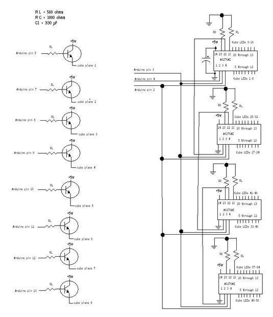
4 A6276EA LED driver chips from Allegro
8 NPN transistors to control the voltage flow, I used the BDX53B Darlington transistor
4 1000 ohm resistors, 1/4 watt or higher
12 560 ohm resistors, 1/4 watt or higher
1 330uF electrolytic capacitor
4 24 pin IC socket
9 16 pin IC sockets
4”x4″ (or larger) piece of perfboard to hold all the parts,
An old computer fan
An old floppy controller cable
An old computer power supply
A lot of hookup wire, solder, soldering iron, flux, anything else to
make your life easier while making this.
7”x7” (or larger) piece of wood used to make the LED soldering jig
A nice case to display your finished cube
My Arduino/Freeduino of choice is the Bare Bones Board (BBB) from www.moderndevice.com. The LEDs were purchased off eBay and cost $23 for 1000 LEDs shipped from China. The remaining electronics were purchased from Newark Electronics (www.newark.com) and should only cost around $25. If you have to buy everything, this project should only cost around $100.
I have a lot of old computer equipment so those parts came off the scrap heap.
Step 2: Assemble the layers
How to make 1 layer (64 LEDs) of this 512 LED cube:
The LEDs I bought were 3mm in diameter. I decided to use small LEDs to cut down cost and to make the final size of the cube small enough to sit on my desk or shelf without completely taking over the desk or shelf.
I drew an 8×8 grid with approximately .6 inches between lines. This gave me a cube size around 4.25 inches per side. Drill 3mm holes where the lines meet to make a jig that will hold the LEDs as you solder each layer.
The A6276EA is a current sink device. This means it provides a path to ground rather than a path to source voltage. You will need to build the cube in common anode configuration. Most cubes are built as common cathode.
The long side of the LED is generally the anode, check yours to make sure. The first thing I did was test every LED. Yes it’s a long and boring process and you can skip it if you like. I would rather spend the time to test the LEDs than find a dead spot in my cube after it was assembled. I found 1 dead LED out of the 1000. Not bad.
Cut 11 pieces of solid, non-insulated hook up wire to 5 inches. Place 1 LED into each end of a row in your jig and then solder the wire to each anode. Now place the remaining 6 LEDs into the row and solder those anodes to the wire. This can be vertically or horizontally, it doesn’t matter as long as you do all the layers the same way. As you finish each row, trim the excess lead from the anodes. I left around 1/8”.
Repeat until you’ve finished all 8 rows. Now solder 3 pieces of hook up wire across the rows you just made to connect them all into a single piece. I then tested the layer by attaching 5 volts to the
hook up wire lattice through a resistor and touched the ground lead to each cathode. Replace any LEDs that don’t light.
Carefully remove the layer from the jig and set it aside. If you bend the wires, don’t worry, just straighten them out as best you can. It’s very easy to bend. As you can tell from my pictures, I had a lot of bent wires.
Congratulations, you’re 1/8 done. Make 7 more layers.
OPTIONAL: To make soldering the layers together (Step 3) easier, while each subsequent layer is still in the jig bend the top quarter inch of the cathode forward 45 to 90 degrees. This will allow the
lead to reach around the LED it is connecting to and will make soldering much easier. Don’t do this to your first layer, we’ll declare that one is the bottom layer and the leads need to be straight.
Step 3: Assemble the cube
How to solder all the layers together to make a cube:
The hard part is almost over. Now, carefully place one layer back into the jig, but don’t use too much pressure, we want to be able to remove it without bending it. This first layer is the top face of the cube. Place another layer on top of the first one , line up the leads and start soldering. I found it easiest to do corners first, then outside edge, then inside rows.
Keep adding layers until you are done. If you pre-bent the leads then make sure to save the layer with straight leads for last. It is the bottom.
I had a little too much space between each layer so I didn’t quite get a cube shape. Not a big deal, I can live with it.
For more detail: How to build an 8x8x8 LED cube and control it with an Arduino