In this post I will describe the hardware and the software part of a project involving the use of BLDC (Brushless DC) motor salvaged from a broken XBox 360. This is a second installment in the series of posts related to Arduino and brushless DC motors. Please see the first part for a bit of info on the theory behind the commutation sequence. Once you understand the commutation sequence for the particular design of the BLDC motor, the circuit design for the BLDC driver becomes pretty clear. It is not much different from a bipolar stepper driver in that we need the be able to both source and sink current at all ends of the windings, except of course in this case there are only three ends whereas the bipolar stepper has four.
The circuit diagram below is a concept that should work with any microprocessor (or a specialized driver IC) that is able to produce the correct commutation sequence:
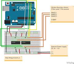 Please note that this is a simplified circuit that only makes use of three MCU outputs. With three driver inputs it is possible to create only two levels at the ends of the windings: LOW and HIGH. Using three different levels – LOW, HIGH and OPEN could have enabled us to disable one of the windings on each of the steps, which results in more torque and also enables rotational speed feedback via measuring voltage induced on the disabled winding by the permanent magnet of the rotor. However, this circuit was designed for a rather simple application where speed feedback is not required – the load is so light that the motor is guaranteed to complete the steps given to it and the rate that the controller sets up. If your application requires accurate speed control and your motor does not have Hall-effect sensors (many BLDC motors do), then this simplified circuit is not suitable for your application. The flip side of the three-level BLDC driver circuit is that it requires six MCU outputs.
Another similarity of this circuit with bipolar stepper drivers is that it’s based on the same quad half-H bridge IC – SN754410 by Texas Instruments (SN754410 datasheet: SN754410 Quadruple Half-H Driver IC).
Here is the Arduino Sketch for driving the BLDC with discrete steps: Arduino sketch for BLDC motors – discrete steps
If you watched through the first part of the video above, you can see that the CD is constantly slipping on the spindle – if the motor is driven in such a way that the driver IC is given each of the 36 steps that comprise one complete 360° revolution, it responds to each step very quickly and half the time just sits there at the step while the CD disk ontop is having a hard time catching up. The friction between the spindle and the CD is just not enough to firmly hold the CD to the spindle and rotate synchronously. In the actual CD/DVD drive there is a small disk spring with several concentric petals that pushes on the CD toward the spindle and helps to prevent the slips. In our case we don’t have such a spring and so we have to devise other ways of gently rotate the spindle so the CD on top of it does not slip.
All these problems with jerkiness (Wikipedia says: Jerkiness, sometimes called strobing – somewhat ironic given that this will be a stroboscope when we’re done) of the spindle are caused by driving it from the binary output (either HIGH or LOW) of the MCU. Three phase motors like these are ideally driven with alternating currents and voltages creating a sinusoidal waveform, 120° apart on each of the three ends of the windings. This requires a lot of effort in a digital world – a DAC chip (Digital-to-Analog Convertor) and plenty of computations. But there is an easier way to “emulate” the effect of alternating current in the binary world of microcontrollers: pulse width modulation or PWM.
PWM is a technique of producing bursts of current at a preset voltage in a rapid succession of cycles of equal length called PWM period which is the inverse of the PWM frequency. The duration of the burst in each cycle, called PWM duty cycle, is defined by the PWM value from 0 to 255 (as implemented in Arduino) where 0 means no burst at all, at 127 the burst continues for 50% of the time of the PWM period and 255 means that the output is on HIGH during the entire length of the PWM period.
The PWM is still a digital output – it has only two states – 0 and 1 AKA LOW and HIGH. However, if we apply this output to a load that has inertia of any kind, such as persistence-of-vision if we control LEDs or moment of rotational inertia if we control electrical motors, the end result of PWM control resembles the effect of controlling the voltage across the load – dimming the LEDs and controlling the RPMs of the motor.
Most Arduino boards have 6 PWM-enabled outputs and Arduino Mega has 14. In our case 3 is enough. The PWM values (PWM duty cycle) are taken from the diagram above. Please disregard the LED flashes for now – they are specific to the project this digram was prepared for. Also, note that this is NOT a sine voltage waveform digram even though it would have been appropriate describing a three phase motor. It would be difficult to create it with Arduino and therefore what you see is a PWM timing digram – PWM duty cycle as a function of rotational angle. Since our motor is a 9-cog, 12 magnetic poles BLDC, each of the PWM cycles (a change from 0 to 255 and back) on the diagram represent 1/6th of one full 360 ° rotation ( please see the first part for a better illustration of why). The number of steps in which we divide the full PWM cycle is rather arbitrary but after some experimentation I settled on 48. I started off with 12 but it did not make the rotation smooth enough. 24 PWM steps were already workable and 48 PWM steps were the most smooth. We could divide it even more but it would be too much of a hassle because I wanted to treat these values as a constant array so as to avoid making the Arduino go through some serious (for an MCU) math calculations to create it. I just calculated the 48 values I needed in the OpenOffice.org Spreadsheet (here is the spreadsheed for the sine function : Sine function spreadsheet in OpenOffice.org Spreadsheet format )
Please see the PWM duty cycle array definition on the highlighted lines in the Arduino sketch below. The rest of the sketch should be pretty much self-explanatory. The windings are marked as A,B and C and they are connected to Arduino’s digital PWM outputs numbers 9,10 and 11 respectively. The Arduino looks up the PWM parameter from the pwmSin array always keeping windings 1/3 of the cycle apart. Once the cycle duration variable, set by the motorDelay constant and additionally corrected by a potentiometer value potState, expires, the program moves one step forward by incrementing all of the winding’s positions and resetting the one that reached 48 back to 0.
For more detail: Brushless DC (BLDC) motor with Arduino – Part 2. Circuit and Software