Can a microcontroller control its own power? Well nearly!
An ATX power supply, either new or from an old PC, is a great way to power Arduino and other microcontroller projects. That is covered in several ‘ibles such as this one. However, because of some of the special features of an ATX, we can use it as a “smart” supply that’s even better.
This is a very simple ‘ilbe that will allow you to make a lead that will allow you to control an ATX power supply from your microcontroller. That way you can use your old ATX as a silent, low-waste power supply for low current microcontroller applications and switch it under firmware control to a high-current monster supplying tens of amps at 5V and/or 12V.
A video showing the idea in action is embedded in the final step.
Total cost of the control lead is a few pounds and you will not damage your power supply in any way so it can be used for other applications later if you wish.
Step 1: Things you need:
This project requires:
An ATX motherboard extension cable (£2 inc delivery from e-bay)
3 jumper leads
A 1K resistor (value not critical)
Some heat-shrink tube
Tools:
Soldering iron & solder
Clippers
Lighter to shrink the heat-shrink
For use:
An ATX power supply
A 5V microcontroller such as an Arduino
High power transistors etc to control stuff.
Step 2: Background
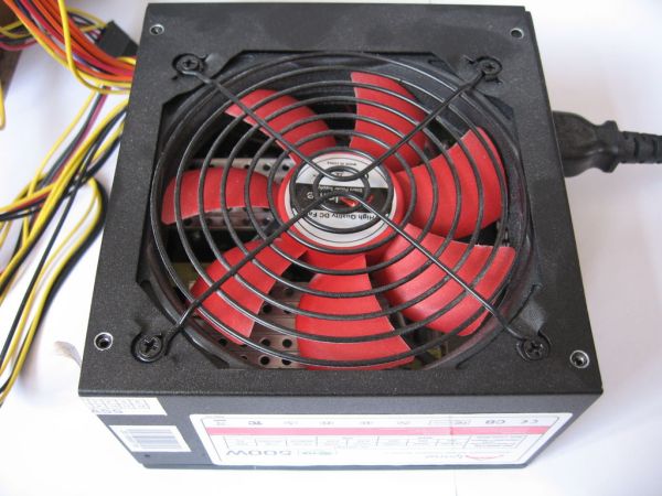
An ATX supply is a wonderful thing!
Looking at the sticker of this supply that I picked up new for £15, we see that it can supply a well-regulated:
20A at 3.3V
30A at 5V
30A at 12V
Plus a stand-by current of:
2A at 5V
Now 2A at 5V is ample to run nearly any 5V microcontroller, while 30A at 5V or 12V is enough to power pretty much anthing short of an aluminium plant.
All we need to do is tap into the 5V standby power to run our controller board and then switch on the high-current supply when we need it.
Step 3: Making up the connector
The ATX power connector is well known and the pinout is available online, such as here:
What we need is the stand-by 5V power (purple), the control wire (green) and any of the black ground wires.

Start with the female end of the connector (well, I take that to be the female end – the one in the first picture) and clip off everything we don’t need close to the connector. Then clip off purple, green and black close to the other end. Slip some hear-shrink over these three and strip these wires and the jumper wires we are connecting to.
We are going to add a 1K resistor to the control wire just because we can and it avoids any risk of excess current flowing when we pull it low with the microcontroller. So, solder the resistor to the green jumper lead and then to the green wire from the ATX extender. Solder the purple and black wires to the corresponding jumpers (in my case red and black). Finally, heat your heat-shrink.
3 jumper leads
A 1K resistor
For more detail: Arduino Controlled ATX Power Supply