Touch-free queue management service powered by Arduino MKR WiFi 1010 and Twilio.
Description
The COVID-19 pandemic has changed the way we interact with people, things, and the world around us. Social distance enablement is one and only effective method to prevent the spreading of COVID-19. The whole developers in the world are trying to create software or hardware related products to wipe out the spreading of disease.
Here we are dealing with the Physical queues. So physical queues are one of the major threats for the social distancing act. Being in a physical queue there are huge chances of spreading the disease. In a certain queue, we need to receive physical tokens from the counter that will also increase the chances of getting the disease. Peoples hate nothing more than standing in queues, uncertain when their turn will come to receive their service. Long queues will probably result in tangles. So maintaining a physical queue is actually a big risk for the service provider(The authority who provides services) and also for the peoples who need to be in the queue.
The virtual queue and tokens are an effective way to handle the queue these days. But most of the virtual queue needs a dedicated complex software and the internet connection. Poor internet connection will probably bring you to the last in a queue. For handling the complex software the person needs little skills.
So here we are introducing the Queue Management Node(QMN) which is a simple user-friendly smart queue maker powered by Arduino MKR WiFI 1010.

Let’s watch the video of QMN.
How Does It Work?
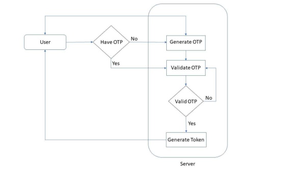
Queue Management Node(QMN) is the device that is creating smart tokens. For creating the smart tokens, the person should be in the wifi range of Arduino MKR 1010. The person also needs a smartphone to get the process done. The workflow will go as follows
- A WI-FI access point will be created by Arduino MKR 1010.
- The person who wants token needs to connect the phone to the access point & that will be redirected to the localhost.
- On that page, the person needs to enter his/her phone number. At that instant, OTP will be sent to the concerned number to verify it. The phone number is taken intentionally to give notification.
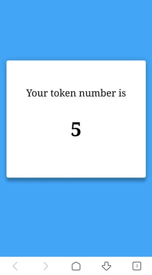
- After verifying the phone number, the token will be displayed on the localhost.
- When his/her turn comes the device(QMN) will send a message notification to the concerned person to take their turn.
This device is actually receiving the request from peoples and giving them the smart tokens. For sending the message we are using a Twilio SMS API in the QMN device. The notification of Turn can be sent by pressing the button in the QMN.
When all the tokens are called out, you can clear the memory by pressing the reset button on Arduino MKR WiFi 1010.
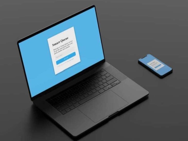
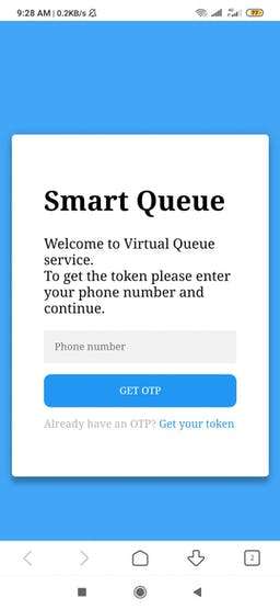
User Interface
When you connected to the AP, you will be redirected to the page like this.
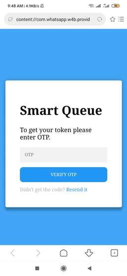
After submitting the phone number, you will get an OTP on that number. Then it shows the OTP page to enter your OTP number.
When you submit the correct OTP, you will get the token on this token page
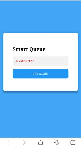
If you entered the wrong OTP, it will show like this
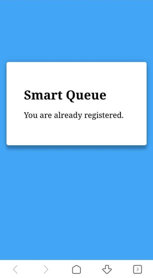
If your number had received the token already, it will load this page
That’s all about the User Interface
Possible Use Cases
- Hospitals
- Shops, Hotels
Advantages
- No internet connection required.
- A simple user-friendly web interface.
- Native device notification, when the turn comes.
- No physical tokens.
- Easy to implement.
- No unnecessary waiting time, show up when your turn comes.
Arduino MKR WiFi 1010
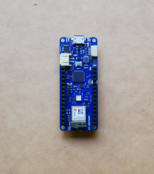
The brain of the QMN is Arduino MKR WiFi 1010. It is the easiest point of entry to basic IoT and pico-network application design. The board’s main processor is a low power Arm® Cortex®-M0 32-bit SAMD21, like in the other boards within the Arduino MKR family. The WiFi and Bluetooth® connectivity is performed with a module from u-blox, the NINA-W10.
This QMN completely relies on the WiFi connectivity of the Arduino MKR WiFi 1010. The device uses both AP(Acces Point) mode and STA(Station) mode of wifi module. The device will intelligently switch between these modes for the proper operation of this device.
Arduino IDE
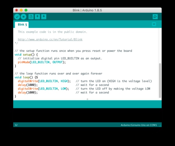
The Arduino IDE is used here for programming the Arduino MKR WiFI 1010. Please have a look here for getting started with the device. Use the latest Arduino IDE for programming the Arduino MKR wifi 1010. Before going into programming check if there is any latest firmware update for the device. Please have a look here to know how to update the firmware.
Captive Portal
We are actually creating an access point (AP) by Arduino MKR WiFI 1010, any device(mobile) can be connected to this AP. Forgoing into the web interface in past, a person needs to type the IP address or hostname in the browser. That’s almost okay, but the user needs to manually put the IP or hostname on the browser. That is a really weird thing. But in this case, the device which is connecting to the QMN will automatically be redirected to the web interface via the Captive Portal. Here the Captive Portal plays a big role in reducing the effort of the user. There are a lot of Captive Portal projects with Espressif devices, unfortunately, there are none with the NINA library. Because the MKR WiFi 1010 uses the NINA library. At last, I found a project in Arduino hub which uses Captive Portal as the key things by JayV Then I began my project by taking it as the base code. It is almost working fine.
What we are actually doing is that we are setting DNS and to own Access Point(AP) – IP address and checking first (16) DNS requests via UDP port 53. After checking the first 16 requests we will send a response for the DNS requests with the redirected IP address of own Access Point. Then the phone will automatically load the web interface through the web browsers. The final effect will be like this when a device connected to the specified AP, the phone will automatically load the web interface. UDP server and Webserver work both at the same time. The web server is a simple main page with a form button for entering the phone number.
Twilio & Things speak

Unfortunately, I don’t have a GSM module to send the messages. For sending the OTP and device notification we need to use any SMS API. So in this project, I used Twilio’s SMS API for accomplishing the task. As we know that, for the API to work we need to give the HTTP request for the server. First I gave normal HTTP request without any encryption to the Twilio, but the Twilio didn’t consider my request. They need SSL fingerprints to ensure security. I didn’t see any functions in NINA libraries which support these SSL’s. So I used Thingsspeak to trigger the Twilio. For using these services you need to register in both the platforms.
In Twilio create a new number and that will be the number in which you sent the data. You will get free credit in Twilio for messaging. For the trial account, you need to verify the numbers in which you want to send the data.
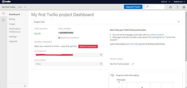
Go to Thingspeak.com, click on apps, then ThingHTTP, and then New ThingHTTP. This will take you to the setup page. You will have to find your Twilio account SID and auth token on your Twilio dashboard page.
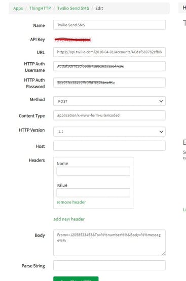
- Name it Twilio Send SMS
- URL is https://api.twilio.com/2010-04-01/Accounts/YOUR TWILIO ACCOUNT SID/SMS/Messages
- HTTP Auth Username is YOUR TWILIO ACCOUNT SID
- HTTP Auth Password is YOUR TWILIO AUTH TOKEN
- Set the method to POST
- Content-type is application/x-www-form-urlencoded
- Click remove headers, and leave host blank
- Body = From=YOUR TWILIO NUMBER&To=%%number%%&Body=%%message%%
Click Save ThingHTTP.
The API key of the ThingHTTp should be included in the Arduino Sketch.
AP OR STA Mode
All the Arduino boards having Nina module do one role at a time i.e Station mode or Access Point mode. We need to constantly switch between these modes to get the job done. First, the QMN will be in AP mode after getting the number it will switch to the STA mode for sending the OTP. After sending the OTP the QMN will switch back to AP mode. If a person triggered the push button, the QMN will switch to STA mode for giving SMS notification. After that, it will come back to AP mode. Forgiving the internet connection we are switching the QMN for STA mode. The SMS API requires an internet connection.
TM1637 4 Bits Digital Tube LED Display & Push Button
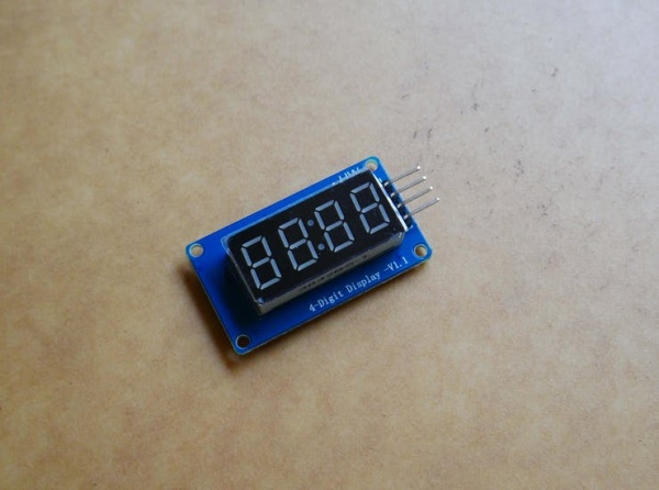
The TM1637 4 Bits Digital Tube LED Display Module is an affordable solution for displaying the output data of your embedded project. Though the data displayed is restricted by numbers still it allows users to display some characters too like A, B, C etc. The current token number which will be running is displayed on this 4-bits seven-segment LED. This 7 segment LED Dsiplayhas 4 digits which are controlled by TM1637 Driver Chip. It requires only two connections to control this TM1637 4 Bits Digital Tube LED Display Module. By looking on this display any one can easily understand the Token number. That’s the real use of this device.
You need a library called TM1637Display.h for working with this module. Just download the library from here.
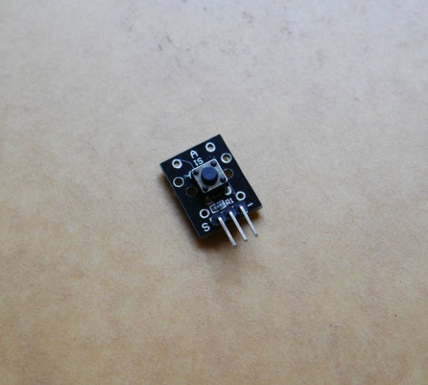
Here push button is used for calling the tokens. I have used the push-button module so it is very easy to integrate. Here the push button is in the pull-down mode. You can easily make a module with a resistor and the push button.
Circuit
The circuit is very simple, it doesn’t consist of any complex hardware. First I made the circuit on the breadboard.
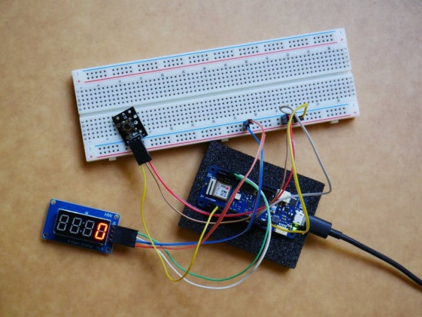
There is only one GND and 5V in Arduino. So we need to give it on the rail for making more connections.
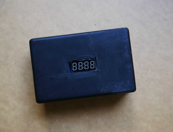
Case
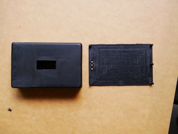
I got this case from a local store. I just cut a small piece in the front for showing the seven segments led for showing the token. I have also torn two-piece from the side one is for the push button and the other is for the USB cable. To giving power for the Node.
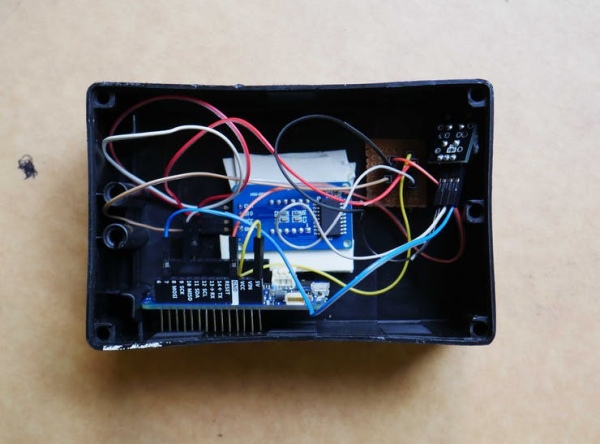
This case is very suiting, All the components are placed very well. The final outlook of the device…
Arduino Sketch
All the HTML pages shown in the interface are stored in the flash memory of Arduino MKR WiFi 1010. For storing that I used the PROGMEM utility.
PROGMEM is part of the pgmspace.h library. It is included automatically in modern versions of the IDE. However, if you are using an IDE version below 1.0 (2011), you’ll first need to include the library at the top of your sketch, like this:
#include <avr/pgmspace.h> While PROGMEM could be used on a single variable, it is really only worth the fuss if you have a larger block of data that needs to be stored, which is usually easiest in an array. We have a large block of data here so we are going for this.
All the HTML files are stored in “source.h” tab. If you want to load your own web page in Arduino, just refer below code.
const char page[] PROGMEM = R"=====(<html>--Your wep page content</html>)=====";You need to call this page on the main programme like this
client.print(page)For put the QMN in AP, and activating the server we are just using these functions
WiFi.config(apip, apip, gwip, IPAddress(255, 255, 255, 0)); WiFi.beginAP(ssid_ap,pass_ap, apChannel); server.begin();Actually, we are configuring web server with constant AP IP address, gateway IP and subnet mask.
When we submit the phone number on the index page the data will be stored to the “number” variable. This is done by means of this piece of code
if (currentLine.endsWith("POST /checkpass.php")) { }After it will load the OTP page. An OTP will be generated by the random function
random(min, max);That will be sent to the phone number by making a TCP connection to the remote host(Thing speak). For making the HTTP request we need to connect the QMN to the internet. ie, To switch to STA mode. For switching the STA mode we are using the function.
WiFi.begin(ssid_sta,pass_sta);When we are switching between these modes, use this piece of code
WiFi.end()That is for clearing wifi memory. Otherwise, it will affect your program.
When the user enters the OTP received, the programme checks whether the submitted OTP and generated OTP are the same by means of this condition
if( otp_gen == otp_sub) {}When they are same it will be added to the Queue array. Actually we are adding that number to the array. The person with that number will be in the queue of the array.
queue[i] = number;Then we clear all those variables to receive a fresh value.
number = ""; otp_gen = "";otp_sub = "";when the user enters the invalid OTP, error page will be loaded. If a number is already in the Queue and that is requesting for another token the device will flag that number and the corresponding page will be loaded.
This is done by means of checking all array elements by this loop.
for (x=0; x<2; x=x+1){if (queue[x] == number){return 0;}}this condition is only executed when there is a valid OTP. If the push button is triggered, the QMN will call the token according to the queue array. That is First in First out(FIFO) method.
What in future?
- Switching of modes can be avoided by using the GSM Module
- Token Forwarding Facility
- Facility for the recall that is the admin can recall the persons who turn is over.
Source: Queue Management Node(QMN)