
Summary of Reading Digital Callipers with an Arduino
This article explains how to interface digital callipers with an Arduino to read measurements via USB, useful for CNC systems. It details a low-cost power circuit using an LED and resistor to replace the calliper's battery, noting voltage logic differences between the 1.5V callipers and 5V Arduino. The text provides specific data protocols for reading binary distance values and sign bits from the clock signal.
Parts used in the Digital Calliper Interface Project:
- Arduino
- Digital Calliper (Precision Gold Electronic Digital Callipers)
- Resistor (About 200Ohm)
- Capacitor (10uF, 2V or more rating)
- LED (Red or IR with ~1.6V drop)
How to use an Arduino to read the signal from a set of digital callipers and send the reading over USB.
Why?
This might be useful for accurate position sensing in home made / hacked computer aided manufacture systems. Adds USB functionality to your callipers.
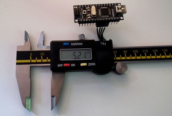
A great reference on reading digital callipers can be found at:
http://www.shumatech.com/support/chinese_scales.htm
What this instructable adds to the shumatech tutorial is:
How to use an Arduino to read the callipers (using very few extra components).
Details of another protocol found to be in use on some callipers.
Basic Arduino code is provided.
To see more of my work please visit j44industries.
Step 1: The Callipers
The callipers I have been working with were the Electronic Digital Callipers by Precision Gold. I bought the callipers from Maplin (item code N48AA) in the UK for just under £20.
After some experimenting with a multi meter and a jyetech oscilloscope (a very cheap basic oscilloscope that can be bought in kit form for under £40) I found the pins to be as shown in the diagram.
Step 2: Voltages: Logic and Power
The Arduino uses 5V logic but the callipers output 1.5V logic. This is a bit of a bodge and may not always work, really a proper logic level conversion circuit should be used but the flowing is a simple hack that worked well with my Arduino:
My Arduino changed between logic high and logic low at about 2.5V (this could vary a bit between boards).
Connecting the positive pin on the callipers to the 3.3V supply means when the clock and data pins are connected to the arduino their voltage seems to vary between 3.3V and 1.8V, which is the Arduino reads as logic high and low respectively.
Powering the callipers with the Arduino:
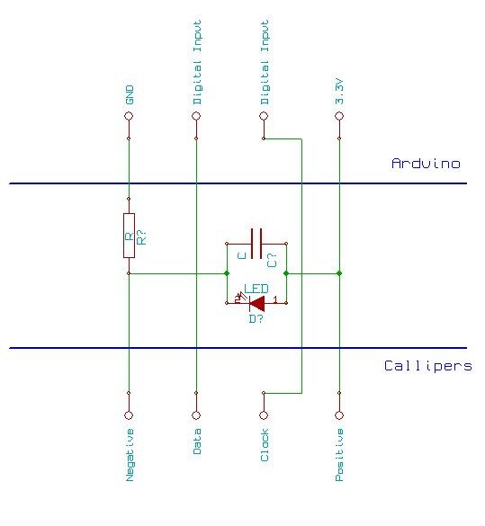
To avoid needing a battery in the callipers the power circuit pictured can be used (remove the button cell). This method relies on using an LED to regulate the supply voltage for the callipers.
Resistor
About 200Ohm
Capacitor
I used a 10uF which worked well, but there would be no harm in using a larger capacitance. 2V or more rating.
LED
For the LED try to find one which has as close to a 1.6V drop across it as possible.
I used a red LED with a 1.8V drop across it. Red and IR LEDs tend to have low voltage drops across them.
Step 3: The Data Protocol
The data protocol used on my callipers was as follows:
Clock pulse as shown in the picture.
Reading the data on a falling clock edge gave a sensible output.
Example data output:
1,0,0,0, 0,0,0,0, 0,0,0,0, 0,0,0,0, 0,0,0,0, 0,0,0,0, (Screen shows 0.00 mm or 0.000 inches)
1,0,0,0, 1,0,1,1, 1,1,1,0, 0,0,0,0, 0,0,0,0, 0,0,0,0, (Screen shows 10.00mm)
1,0,0,1, 0,0,1,1, 0,0,0,0, 0,0,0,0, 0,0,0,0, 0,1,0,0, (Screen shows -1.00mm)
1,0,0,0, 1,1,0,0, 1,0,1,0, 1,1,1,0, 0,0,0,0, 0,0,0,0, (Screen shows 150.00mm)
Interpretation of data:
?,X,X,X, X,X,X,X, X,X,X,X, X,X,X,X, ?,?,?,?, ?,Y,?,?
? = Not sure
X’s for a binary number with least significant bit at the start of the string. The binary number is the distance in mm times 100.
Y = Sign bit if Y = 1 number is negative if Y = 0 number is positive.
Note: make sure the callipers are set to mm the inches mode behaves very similarly except the least significant bit is used to show 1/2000ths of an inch.
Arduino
For more detail: Reading Digital Callipers with an Arduino
- Why use an Arduino with digital callipers?
To enable accurate position sensing in homemade computer aided manufacture systems and add USB functionality. - How do you power the callipers without a battery?
Use a circuit with an LED and resistor to regulate the supply voltage from the Arduino. - What components are needed for the power regulation circuit?
A 200Ohm resistor, a 10uF capacitor with at least 2V rating, and an LED with a low voltage drop like red or IR. - How does the voltage logic difference affect the connection?
The callipers output 1.5V logic while the Arduino uses 5V; powering callipers with 3.3V allows the Arduino to read them correctly as high and low states. - When should the data be read relative to the clock pulse?
Reading the data on a falling clock edge gives a sensible output. - How is the distance value calculated from the binary data?
The binary number represents the distance in mm times 100, with the least significant bit at the start of the string. - How can you determine if the measurement is negative?
If the Y bit equals 1, the number is negative; if it equals 0, the number is positive. - Does the inches mode work differently than millimeters?
Yes, in inches mode the least significant bit shows 1/2000ths of an inch instead of millimeters.
