Today, I constructed a compact 3x3x3 LED cube utilizing an ATtiny2313 that I acquired around 2 weeks ago. Every time I wanted to update the LED cube with better patterns, I had to bring out my breadboard, reconnect everything following ATtiny2313 pin-outs, and upload the updated code.
I proceeded to search on eBay and Amazon for a device to program these chips since I intended to use them frequently in the future. I wasted an hour before realizing I couldn’t justify spending 20-30 dollars on a basic shield.
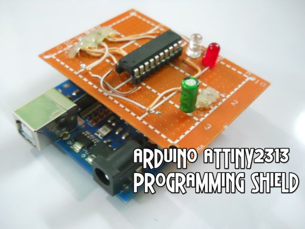
After some consideration, I opted to create a straightforward and convenient ATtiny2313 programming shield. Once it was constructed, all I had to do to reprogram any of my attinys was to place it in the programming shield and with just a few clicks, the code would be uploaded. There is no need to be concerned about whether all the connections are correct and ensure there are no short circuits or any other issue that could damage the chip or any other components.
In this guide, I will demonstrate how to construct a shield like this for your own use!
It requires minimal cost and can be made in just around 30 minutes.
Let’s begin now!
Step 1: Materials
Tools required for this project;
- Soldering Iron
- Solder
- Glue Gun (Or just good glue)
Step 2: Prototype and Pinout
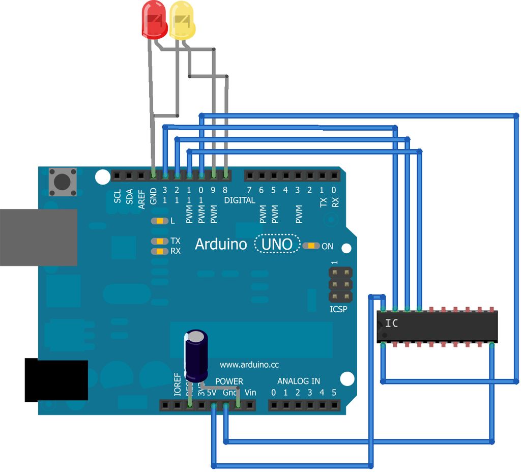
The diagram illustrates how to connect all components together by following the pin-out diagram, connecting everything to a protoboard with headers that can be placed on the arduino as a shield instead of directly.
Ensure the pin-out diagram of the ATtiny2313 is close by while connecting everything to prevent potential forgetful mistakes.
Image showing the pin configuration of ATtiny2313 sourced from http://blog.williambritt.com/uploads/attiny2313-pinout.png.
Step 3: Working on the actual shield
Begin by connecting the female headers to the middle of the protoboard, followed by inserting the male headers into the arduino. Next, place the protoboard onto the arduino to determine the precise location for soldering the male headers.
Next, attach the male header pins to the female headers based on the pin-out diagram (Female headers will connect the ATtiny2313 while male headers will connect the shield to the Arduino).
Next, attach the 2 LED’s and the capacitor and wire them following the pin configuration. Ensure the correct orientation of the polarized capacitor.
After everything is properly connected to the arduino and a test code is uploaded to ensure proper functionality (instructions for this in the next step), apply hot-glue to the solder joints to secure them and prevent any incorrect connections. Another option is to utilize electrical insulating gel/adhesive.
Materials required for this project;
- Protoboard
- 10 Micro Farad Capacitor (or similar value)
- 2 LED’s
- A couple of wires
- A single row pin header strip
- A single row female pin header strip
For more detail: Arduino ATtiny2313 Programming Shield