Summary of Analog Input using Arduino
This project demonstrates how to use a potentiometer connected to an Arduino's analog input to control the blinking rate of the built-in LED on pin 13. By wiring the potentiometer’s outer pins to 5V and ground and its wiper (middle pin) to analog input 0, the Arduino reads the varying voltage levels as analog values. These values adjust the delay timing between LED blinks, allowing the user to control the blink speed by turning the potentiometer. The example requires no additional resistor for the LED due to the low current on pin 13.
Parts used in the Arduino Potentiometer LED Blink Project:
- Arduino Board
- Potentiometer
- Built-in LED on pin 13
A potentiometer is a simple knob that provides a variable resistance, which you can read into the Arduino board as an analog value. In this example, you’ll connect a poterntiometer to one of the Arduino’s analog inputs to control the rate at which the built-in LED on pin 13 blinks.
Circuit
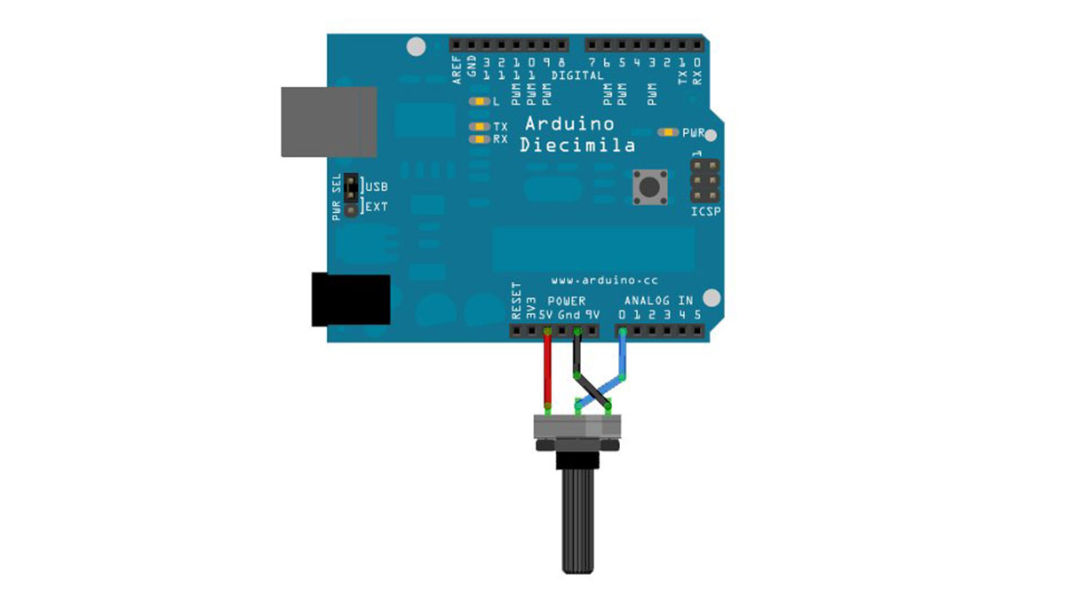
image developed using Fritzing. For more circuit examples, see the Fritzing project page
Connect three wires to the Arduino board. The first goes to ground from one of the outer pins of the potentiometer. The second goes from 5 volts to the other outer pin of the potentiometer. The third goes from analog input 0 to the middle pin of the potentiometer.
For this example, it is possible to use the Arduino board’s built in LED attached to pin 13. To use an additional LED, attach its longer leg (the positive leg, or anode), to digital pin 13, and it’s shorter leg (the negative leg, or cathode) to the ground (gnd) pin next to pin 13. Because of the low amount of current coming from digital pin 13, it is not necessary to use a current limiting resistor in this particular case.
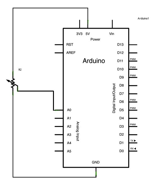
Schematic
Code
In the beginning of this program, the variable sensorPin is set to to analog pin 0, where your potentiometer is attached, and ledPin is set to digital pin 13. You’ll also create another variable, sensorValue i to store the values read from your sensor.
The analogRead() command converts the input voltage range, 0 to 5 volts, to a digital value between 0 and 1023. This is done by a circuit inside the Arduino called an analog-to-digital converter or ADC.
By turning the shaft of the potentiometer, you change the amount of resistance on either side of the center pin (or wiper) of the potentiometer. This changes the relative resistances between the center pin and the two outside pins, giving you a different voltage at the analog input. When the shaft is turned all the way in one direction, there is no resistance between the center pin and the pin connected to ground.
Hardware Required
- Arduino Board
- Potentiometer
- built-in LED on pin 13
For more detail: Analog Input using Arduino