We are changing the way we use the STONE Trademark LCD with the Arduino. You can connect to the official page of the LCD. These screens will communicate with UART or RS232 as if they were on the same Nexton screen. If I were to do a comparison, the Nextion display has some extras and minors. I think the biggest minority editor does not have a simulator. A feature that speeds up testing when simulating animations and widgets. The manufacturer has not added this feature to the editor yet, but it may be added in the future. Other than that, the programming of the second-minus LCD may not be done through a series of reports. This feature allows online updates to engage remote systems via Linux or Windows-based systems. The STONE monitor module has more widgets, if I can change it more. As rich as the box. Regardless of whether it works for contacts or not, and whether it supports background bitmaps or not, it’s probably my favorite feature. Also, my first discovery suggests that the STONE LCD is more valuable for communications than the Nexiton. Also, pushing a button to send quick data to the next screen could cause problems. I haven’t had any such problems with the STONE LCD, but the free STONE bookmarklet is a little more than the Nextion screen. So for a hobby, the Nextion may be a better choice.
Let’s examine the screen in more detail.The Flash Bellek input box provides examples of applications, videos and necessary programs. If you don’t have the next device or call the latest version, you can access many things that need to be connected. You can apply the necessary screen design applications from the connection specified by the name “20191019-TOOL 2019“. (This name may have changed on the following date.) When you open the application, the following is displayed.
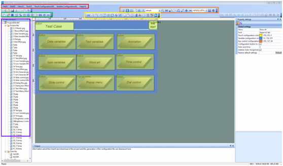
The images also have a very complex interface. Each application has a red file and directory component. I do not intend to discuss these in detail. This key specifies the “screen configuration” that will be used for the left mouse button in the login screen. When you press this button, you will see the screen like this.
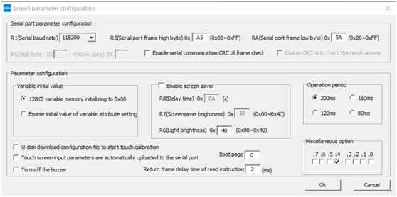
You can specify the serial port and the initial bytes when communicating with the serial port on this settings screen. The serial port communication speed sets the observation rate that we all know. This speed must be the same as the miniature general purpose computer or host computer that we use to properly report. The first values of R3 and RA for the serial port frame buffer are the high and low values that the screen will send you when you press any button on the screen. Similarly. when you send a message on the screen. For example, if you use the editor to load the design on the screen and use the serial port to notify the widget on the screen, you will see the data type “0xA5 0x5A 0x82…” on the serial port. It is important that the data from the serial port is not ASCII characters. They are byte data. So you can’t see these ASCII serial port interface values, just like the Arduino serial port screen. I recommend that you use an application such as SSCOM or REALTERM. You can reset the initial values of the screen changes again on the screen under the “Parameter Configuration” heading. Or you can activate the buzzer that sounds every time you touch the screen by checking the checkbox on the left. At the same time, it is important to enter a value for the “boot page” with another important feature. Currently, the value “0” is written there. This means that the image will be opened with the “0” and the name of the image will be on the left side of the previous image. If the input is incorrect, you will only see the error code on the screen. I have not yet found a document that contains the meaning of these errors. If I can find one, I will share it with you.
After this section, let’s go to the “Generate profile” button to the right of the “Screen profile”. This button creates a file that will load the screen using the design in the editor. When you do this he will do a little drawing process to tell you if there are any errors in your design. You must click this button to make any changes to my design or settings on the screen. When you press this button, a folder named “VT_SET” will be created where the project files are. The design files in this folder need to be uploaded to the LCD. There are two ways to load these files to the screen, the first way is to put a complete USB memory in it. The second method is to connect to the LCD with the help of a USB cable.I used this method for a quick test. In the first stage of design, I recommend you to do this. You can click on the “Generate Profile” button two places to the right of the “Online Download” button and upload it when you connect the USB cable.
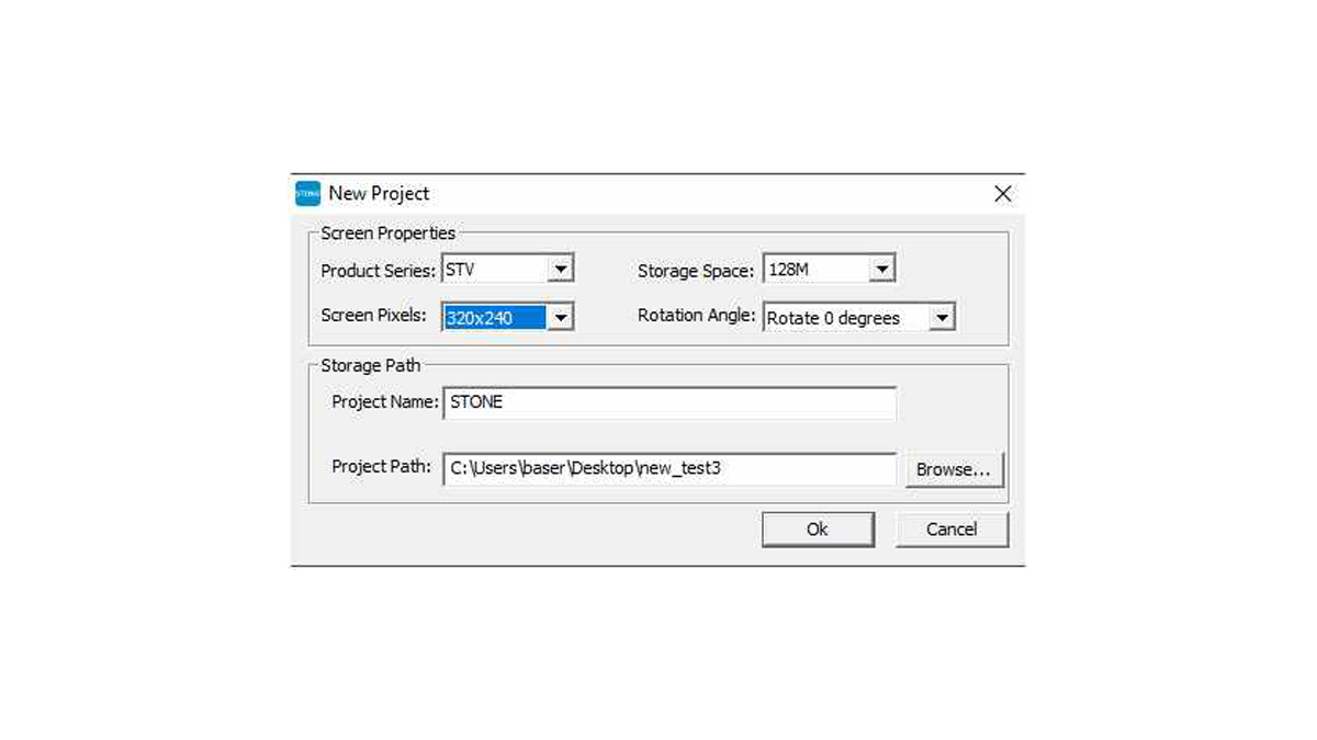
Now it’s time for the design part. In this section I will use the design we used for the Nextion screen. Add another page to the gauge widget. First, create a project. To do this, you need to press the “New Project” button under the “File” menu and then select the properties of the screen in the window that opens. You can also specify the location and name of the project on this screen.
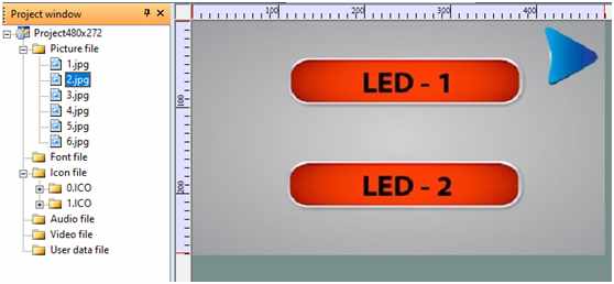
First, let’s add the images that make up the page and the background. To do this, you need to right-click on the Image File section of the image above and then click on the Add option. You can add the images that you want to add to the project to the project. The file name will be 1.2.3. Please simplify the image selection for the project. If you want to change the image in the previous step of the project, right-click on the image and say “Replace”. But make sure that the resolution of the image you add in the project does not exceed the screen resolution. Otherwise, you may encounter errors. The image I created is shown below.
In a moment, let’s add a widget which adds a widget to the contents of the toolbox, the green and yellow boxes are shown in the image above. There are several buttons available in the “Design Editor”. Each button has a different purpose and applies to the basic process, e.g. the “button” on the left is the “green” button. In this editor, pressing a button in the Nextion editor will create an effect. When you add a button to an effect, or when you click on a widget and you have to enter an image, it will use the button on the left. So when you press it, it will break down and appear. Reaffirming the position is useful. In these editors, the same background will load in two different ways to produce the button effect. The first image shows no print button. In the second image, when you press the button, the button will be placed in the form requesting it to be displayed. Therefore, you can select the second image of the button and then press each button to display another button in the image.
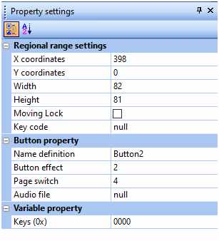
The diagram above shows how to make settings on the editor for these settings. I won’t be changing any other settings. This button type has no more settings than the ones used for simple processes, like transitions between pages. Now we’re going to send a command to the Arduino to make the LED burn and go off. Unlike the previous button, this button has an address in memory. When you press the button, you send this address information via UART. On the buyer side, you can see which button is pressing the address value you entered. To add this button, we add a second “Return pressed key value” tool to the first green field in the image. When we select an area that we want to capture in the design, like in the previous button, we assign the button property to that part of the image.
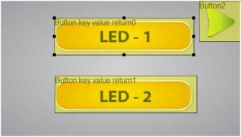
As you can see, I’ve given the button a 16A1 number for the address. This number will be in hexadecimal and 16 bits. So you can provide an address as most 0xFFFF. two buttons appear at the top of the screen. The green button is called “Button2” which means “button key value return*”. These buttons have address buttons and when we click on them, they will send out their address value on the UART.
So let’s make the first page very simple. Let’s use a text box and a toggle button on the second page. The toggle button is a little more complicated to use than the next screen. Because it’s complex, the widget we use for the toggle button will also be working on different processes at the same time. If we can’t use the other functions, we need to make the necessary settings. The other page looks like this.
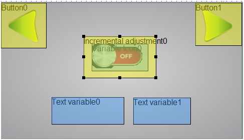
A widget called “Incremental adjustmen0”, which is used when the toggle button is an image, is shown in the picture. This alone is not enough to perform the switch button operation. There is a variable icon below. When you click on the first widget, the second button will perform the change in the icon view. The two widgets that perform this action must have the same address. Since they are on the same button, these vehicles have the address values we have assigned. The two vehicles have the properties shown in the picture below.
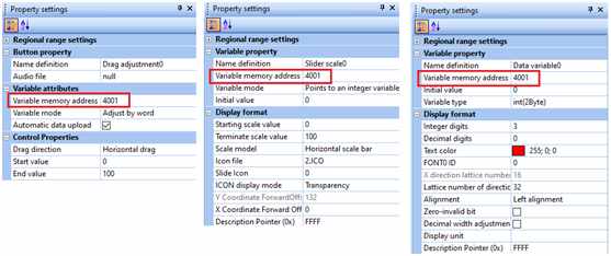
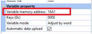
The image on the left is the image of the “Incremental Adjustment Menu 0” and the image on the right is the property of the “Variable Icon”. As shown above, the address value of both widgets is “1992”. Both widgets are arranged as 0 and 1 on the upper and lower borders and their value is increased by pressing one of the left keys to select “++”. Progress bars, etc. You can make tools, and you don’t need to record pictures of the different percentage languages of the widgets when you make a progress bar. All we have to do is to record two images of the state of the switch, as it is on and off. Here is an important detail. Images without “png” vb background are not supported by the default screen to be used. But if you load any icon file here, the background will be black and the black part will only be seen by the icon itself, which I would like to point out is a beautiful and useful feature. When you name the icons, you can easily use names like “0.1.2.3…” in toggle or progressbar designs.
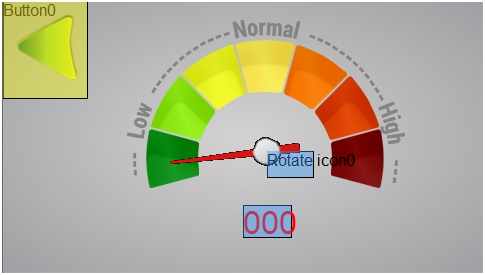
The text widget has no complex state. The length of the text you send is only important when sending data. The properties of the text widget are open and understandable. This section is up to 3. last page. Three. I have used a display on the page where I will show you the ADC values I measured using the Arduino. The third one is designed by me. Here is a screenshot of the page.
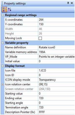
I used a “Rotate Icon” and a “Data Variables” widget, the background image is an image added to the background using Photoshop. So the image is added on top of the button and there is no additional widget. Here are some settings for the “Rotate Icon” widget. Below is the image that is specified by the properties of this widget. The main function of the “Icon Rotation Center” is in these properties. After selecting the icon view to be rotated with the “Icon File” button, you can click on “Icon Rotation Center”. An image of the icon we selected on the open page will appear. In this image, we have to select the center of rotation of the icon. So the next value is that the icon will rotate around the center. At this point, if you want the icon that you’re designing to stay at 0 degrees, you have to record it like this. So you don’t have to set 0 degrees, so if you want to set the icon, you can record it that way.
The use of data variables is a simple widget. No other settings are required. You can only select the number of parameters that you want to reflect. After that, we come to the hardware area. The communication protocol of the LCD connected to the desired hardware section is very important. I use RS232 to communicate with the outside world. So it is not possible to link the Arduino or similar microgene. In fact, there is no communication other than RS232UART. However, it is used for UART with very high tension rate. So we need a revolution in MAX232 integration to change the stress level. Since I don’t have a MAX232, I solved the problem with the following connection scheme, or you can solve your problem like this.
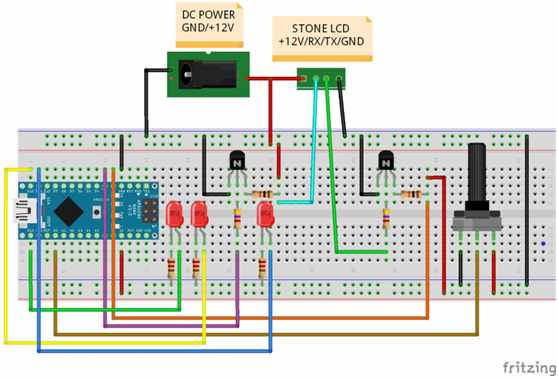
It seems that this revolution just needs to change the logic level. I mean, we need this pathway to increase the 5V vocabulary from Arduino to 12V and to increase the 12V vocabulary from LCD to 5V. in fact, the MAX232 circuit doesn’t work much differently. The transistor used in this direction is NPN, and there is a pin structure on the left with an emitter, base and collector. We say it is possible to change the program. The other 3 LEDs are used for buttons. We also contacted the software department. Part of the software only contains serial communication and data sharing. So it is not top complex. The most important data formats are considered part of the software. the STONE LCD uses the following data formats.
[header 1, header 2, packet length, data type, address 1, address 2, data length, data 1, data 2]Header1: first part of a series of 16-bit headers, written to screen parameters
Header2: second part of the 16-bit header series, write screen parameters
Packet length: the length of the sent or received data. If sending data, you must calculate the length of the sent data and write with this value.
Data type: the command section written in the screenshot guide shows its function. This command can take a value between 0x80 and 0x83.
Address 1: We say that the address of the widget on the screen is 16 bits. The first 8 bits of this address value
Address 2: Auxiliary 8-bit for widgets
Data length: the length of the data sent from the component as a 16-bit packet
Transmits the received data to 1 or 16 bits. This is the first part of the 16 plant data
Data 2:16 bit rate Part II data
This is also true when sending this data format. There are exceptions to this. For example, if you send a letter, instead of 16 bits, it’s 8 bits because all the values in the ASCII table are 8 bits, so you don’t have to send 16 bits of data.
This is how I first formed some of the screen data in the software. We’re checking to see if there’s any data in the buffer. If there’s any data, we’re checking to see if the data is appropriate this time around, so if the head of the packet, then we’re checking.
if (displaySerial.available()) //check Serial Port buffer
{
if (readSerialByte() == 0xA5) //Check first data is 0xA5
{
if (readSerialByte() == 0x5A) //Check second data is 0x5A
{
uint8_t dataLen = readSerialByte(); //Read packetlen from first byte
uint8_t sendCmd = readSerialByte(); //read cmd from second byte
uint16_t dataAdr = (readSerialByte() << 8) | //read and merge 16 bit data from buffer
readSerialByte();
uint8_t valLen = readSerialByte(); //dataLen get
uint16_t mVal = 0;
for (int i = 0; i < valLen * 2; i++) //get all data from buffer with loop
{
mVal = mVal << 8;
mVal |= readSerialByte();
}
parseCMD(dataAdr, mVal); //toggle LED with incoming data
Serial.print(dataLen); //debug values
Serial.print(” “);
Serial.print(dataAdr, HEX);
Serial.print(” “);
Serial.println(mVal);
}
}
}
The code block above allows processing to be performed according to the partial parseCMD function. So the button on the screen determines which part of the LED will be done in this function, this is done by looking at the address of the switch box.
void parseCMD(uint16_t mAdr, uint16_t mData)
{
switch (mAdr) //check which button pressed with memory adress value
{
case 0x16A1: //button1 adress
digitalWrite(led2, !digitalRead(led2));
break;
case 0x16A2: //button2 adress
digitalWrite(led3, !digitalRead(led3));
break;
case 0x1992: //switch adress
digitalWrite(led1, mData);
if(mData) //send string value according to switch status
{
displaySerial.write(arrOn, 15); //send array on string value
}else{
displaySerial.write(arrOff, 15); //send array off string value
}
break;
}
}
Finally, let’s read the potentiometer data to change the displayed value and send it from the serial port. The point at which the ADC data is monitored is 10 bits. If the UART is bytes, then communication takes place. So we have to split the ADC data into two bytes to send.
if (millis() – lastTime > 100) //send data with 100 ms interval
{
adcVal = analogRead(A0); //read adc value
adcVal = map(adcVal, 0, 1023, 0, 380); //change ADC value limit to 0-380
uint8_t sendValL = adcVal & 0xFF; //get adc value LSB
uint8_t sendValM = (adcVal & 0xFF00) >> 8; //get ADC value MSB
arr[6] = sendValM;
arr[7] = sendValL;
displaySerial.write(arr, 8); //send adc value with Serial port
lastTime = millis();
}