*NOTE* THIS PROJECT IS DONE BY A GROUP OF STUDENTS FROM SINGAPORE POLYTECHNIC.
Telemetry – Solar Cells
Our project is using Arduino with the ZigBee to transmit and receive data from the solar cell. Data will be shown in the LCD and the software called “X-CTU”.
Components used:
1 Arduino Uno
1 ZigBee Shield (Transmitter)
1 ZigBee (Receiver)
1 LCD Monitor
1 Solar Cell
1Resistor (Value may change)
Instructions:
1. Test for Solar Panel
2. LCD Pins
3. Code Used
4. ZigBee Dual Communication Setup
5. Solar Cell and LCD Shield
6. Mounting all the Parts Together
7. Results
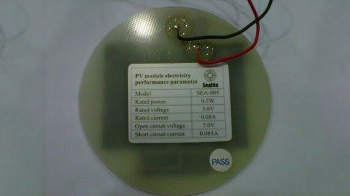
Test for Solar Panel
1. Check the reading of the Open Circuit Voltage and Short Circuit Current at the back of the solar panel.
2. Clip the positive lead from the multimeter to the positive output from the solar panel, and the negative lead to the negative solar panel output.
3. Place the solar panel directly to a bright and consistent light source, such as a desk lamp
4. Turn on the multimeter and set to detect volts. The resulting value should be close to, if not exactly the same as the Open Circuit Voltage reading. As the solar panel is tilt away from the light source, the reading should drop gradually.
5. Configure the mutlimeter to read current by moving the positive lead. Turn on the multimeter and set to detect currents. The resulting value should be close to, if not exactly the same as the Short Circuit Current reading. As the solar panel is tilt away from the light source, the reading should drop gradually.
Step 1:
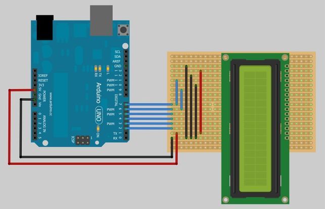
LCD Pins
1. Connect the following LCD pins to the respective pins on the Arduino
– LCD RS pin to digital pin 7
– LCD Enable pin to digital pin 6
– LCD D4 pin to digital pin 5
– LCD D5 pin to digital pin 4
– LCD D6 pin to digital pin 3
– LCD D7 pin to digital pin 2
– LCD D1, D3, D5, D16 pins to Ground
– LCD D2, D15 pins to Vcc
Step 2:
ZigBee Dual Communication Setup
We are going to use 2 ZigBees to communicate with each other, the left ZigBee is used as a transmitter, which is plug into its ZigBee shield and connect to Arduino. The right ZigBee is used as a receiver which is plug into the board with FTDI USB port to connect to the PC.
Firstly, we will need the software called ‘X-CTU’ to do the modem configuration of ZigBee.
Free download available here: http://www.digi.com/support/productdetl.jsp?pid=3352&osvid=57&s=316&tp=5&tp2=0
Step 3:
When we first plug the ZigBee with USB to PC, the PC will install the driver and new COM port itself and X-CTU will also be able to detect the respective COM port of the ZigBee.
There will be no problem with the receiver ZigBee, we can straight plug in and use. But as for the transmitter ZigBee, there are a few things to take note.
– Change the Jumper
There are 3 pins jumper at the corner of the ZigBee shield labeled as XBEE/USB. If we want to configure the ZigBee modem we need to put the jumper at the USB pair, and change back to XBEE pair after configuration.
1 ZigBee Shield (Transmitter)
1 ZigBee (Receiver)
1 LCD Monitor
1 Solar Cell
1Resistor (Value may change)
For more detail: Telemetry with solar cell using an Arduino