what:
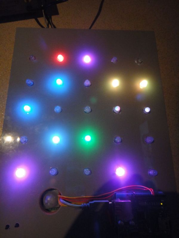
a 5*5 rgb led matrix, made with arduino and lpd6803 based leds from adafruit.
with an pir sensor, it goes on if it detects movements and a ir distace sensor, 1 animation shows the distance you have from the sensor :).
why:
because its beautiful and cool 😉
my spelling:
well, sorry if i make stupid spelling mistakes, i’m dyslectic and live in Holland
Step 1: How it works
how it works:
it uses an arduino uno that controls the lpd6803 chips in the rgb leds, so i can set each led individually. the arduino reads text files from an sd card, i’ve made a program(in c#) where you can make animations and store them so the arduino can read them.
Step 2: Materials needed
materials:
-arduino uno (other arduino’s probbably work, but i havent tested)
-25 rgb leds with lpd6803 controllers( the led’s i used arent being saled anymore 🙁 these are an newer version, but you will need to adapt the arduino code a bit)
-network shield(for sd card)(probably other shields with sd cards wil work)
-5v dc power supply min 1A
optionally:
–ir distance senso r (1 animation uses it)
–pir senso r (the matrix will go on if it detects motion(saves a bit of energy))
-2 pushbuttons
tools:
-soldering iron
-wire stripper
-some wires
-wooden board
Step 3: Part with wood
this is the part im bad at, but ill discribe what ive done:
iv’e put my led’s 5cm apart (horizontally and vertically) in a shiny wooden plate from an old kitchen.
the led’s from adafruit need 11mm holes(drill them carfully).
at the bottom ive place my arduino with double-sided thape, and left of it a big hole for the pir sensor, the ir distance sensor is placed on top(now it looks like it has eyes 😉 )
then put the led’s in the holes beginning top left(frot vieuw) going from left to right down(see picture)
Step 4: The electronics
wiring
led’s clock –> 6
led’s data –> 7
pir sensor –> A5 (if you have no pir sensor, connect it to the 5v+)
ir distance sensor –>A4 (if you don’t have a distance sensor juslt leave it open)
gnd –> Button 1 –> A0
gnd –> Button 2 –> A1
sd: (the default of the ethernet shield)
mosi –> 11
miso –> 12
clk –> 13
cs –> 4
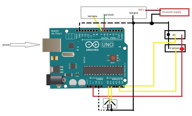
power:
ir distance senor + —–> all to arduino’s 5v+
pir+
ir distance sensor –
pir – —–> all to arduino’s gnd
negative from 5v power supply
led’s –
button –
led’s + —-> positive from 5v power supply
—————————————————————-
all black cables are soldered together as central gnd
all red cables(exept one) are soldered together as sensor 5v+ (from arduino)
all yellow cables are signal cables(watch it are 5 yellows so don’t mix them up!!)
—————————————————————-
you also find mine animations here, just put them on the sd card