It can even be interactive based on the programming.Parts:
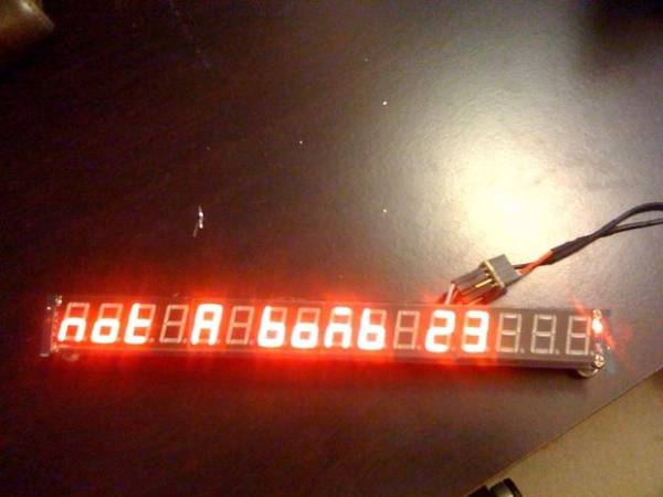
($7.60) 16 Digit TM1640 based display
Dealextreme.com SKU: 104311
http://www.dealextreme.com/p/jy-mcu-16x-digital-tube-yellow-led-module-104311
($2.50) Atmel ATtiny85
Digikey PN: ATTINY85-20PU-ND($1.73) Extra long female header pins
Digikey PN: SAM1209-12-ND
– I got longer sections, as I plan to use these for other projects. ($8.75) Digikey PN: SAM1198-50-ND for 40-Pin headers.
($0.13) 8-pin IC socket
Digikey PN: A100204-ND
NOTE: I suggest you experiment with a different 8-pin socket. This one requires quite a bit of force to insert and remove your chip. It’s easy to bend the ATtiny’s pins when doing this.
Although you should have no reason to remove the ATtiny85 after you’ve got the final breadboard. The chip can be used and programmed in-circuit.
($1.50) Perfboard / Veroboard / valley of holes. Individual solder pads.
Sparkfun PN: PRT-08808
– I opted for a bigger ($12) piece from Digikey, as I wanted it for other projects. (Digikey PN: V2012-ND)
Total: $13.46 – You’ll have some extra long header pins for use with other projects. These header pins are perfect for Arduino shields.
You will also need:
-Soldering iron
-Solder
-ATmega328 based Arduino. I used an Official Arduino UNO R3.
(You can alternatively use another ISP for the ATtiny85)
-5v Switching power supply if you want to use the display as a standalone device.
-Breadboard (optional) – You can program the ATtiny in the completed circuit/holder with wires directly to the arduino.
2. Download Arduino v0023
You can get both of these from Arduino.cc3. Extract both to separate folders on your desktop.4. Download and install the TM1638/TM1640 library from here:
http://code.google.com/p/tm1638-library/
5. Place it with your other arduino libraries **ON ARDUINO v1.0**
Google if you do not know how to install a Arduino library.
6. Install ATtiny45 / ATtiny85 support in **Arduino v0023**
– Download: attiny45_85.zip
http://hlt.media.mit.edu/wp-content/uploads/2011/06/attiny45_85.zip
– Locate your Arduino sketchbook folder (you can find its location in the preferences dialog in the Arduino software)
– Create a new sub-folder called “hardware” in the sketchbook folder.
– Copy the attiny45_85 folder from the attiny45_85.zip to the hardware folder.
– Restart the Arduino development environment.
2. Under the Examples menu item, choose ArduinoISP option
3. Program the arduino with this sketchNote: I had to perform this step in Windows XP. Something about Mac OSX refreshing the connection gave me trouble.
Step 1: A note on soldering.
Before we start, I want to say that this is my first EVER attempt to solder on a piece of perfboard/veroboard.
I’ve soldered wires together a handful of times before though.
Although the connections seem small, just take your time and try to steady your hand! You’ll be fine.
If I can do it, so can you
Step 2: Step 1: Arduino software, libraries.
1. Download Arduino v1.0
2. Download Arduino v0023
You can get both of these from Arduino.cc
3. Extract both to separate folders on your desktop.
4. Download and install the TM1638/TM1640 library from here:
http://code.google.com/p/tm1638-library/
5. Place it with your other arduino libraries **ON ARDUINO v1.0**
Google if you do not know how to install a Arduino library.
6. Install ATtiny45 / ATtiny85 support in **Arduino v0023**
– Download: attiny45_85.zip
http://hlt.media.mit.edu/wp-content/uploads/2011/06/attiny45_85.zip
– Locate your Arduino sketchbook folder (you can find its location in the preferences dialog in the Arduino software)
– Create a new sub-folder called “hardware” in the sketchbook folder.
– Copy the attiny45_85 folder from the attiny45_85.zip to the hardware folder.
– Restart the Arduino development environment.
Step 3: Program Arduino-as-ISP to your Arduino
. Start up your copy of Arduino v0023
2. Under the Examples menu item, choose ArduinoISP option
3. Program the arduino with this sketch
Note: I had to perform this step in Windows XP. Something about Mac OSX refreshing the connection gave me trouble.
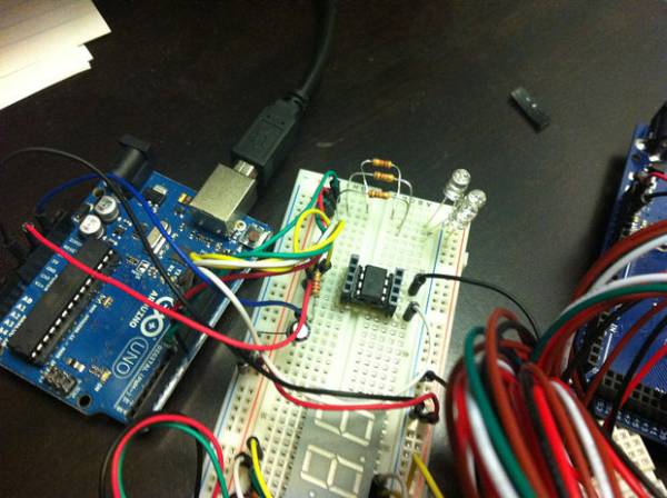
Step 4: Wire up your Arduino to program the ATtiny85
This site is also good reference:
http://provideyourown.com/2011/arduino-program-attiny/
The connections are:
ATtiny Pin 2 to Arduino Pin 13 (or SCK of another programmer)
ATtiny Pin 1 to Arduino Pin 12 (or MISO of another programmer)
ATtiny Pin 0 to Arduino Pin 11 (or MOSI of another programmer)
ATtiny Reset Pin to Arduino Pin 10 (or RESET of another programmer)
You can also wire up LEDs to show your programmers status. Use 1K ohm resistors between the LEDs and Vcc.
Arduino Pin 9: Heartbeat – shows the programmer is running
Arduino Pin 8: Error – Lights up if something goes wrong (use red if that makes sense)
Arduino Pin 7: Programming – In communication with the slave (use green if you like)
Connect a 120ohm resistor between the arduino Reset pin and +5v. This will prevent the arduino from resetting before it can program the ATtiny85.
Some have had success with a 10uF capacitor between the arduino Reset pin and Ground.
For more detail: Self-contained 16-Digit display – Arduino & Attiny85