Summary of Arduino Controlled RGB LED Dot Matrix Board
This DIY project creates a large, foot-treadle music board using Arduino technology. It allows users to generate beats by stepping on pressure-sensitive pads made of aluminum foil and foam. The system employs two Arduino Uno boards for efficient data processing and LED control, utilizing multiplexing techniques to manage 18 RGB LEDs and 18 buttons without overwhelming the microcontroller's limited pins.
Parts used in the Arduino Controlled RGB LED Dot Matrix Board:
- 12" X 24" Plywood board
- 12" X 24" X 1/16" Plexiglass sheet
- 12" X 96" Sheet of aluminum foil
- 6 Different colored wires (braided and non-braided)
- 18 Common Anode RGB LEDs
- 18 3" X 3" sheets of 1/4" foam
- 2 Arduino Uno boards
- 4 TLC5940 Microcontroller chips
- 1 Blank PCB
- 6 10+KΩ resistors
- 4 8.2 KΩ resistors
This project is a relatively straightforward and simple DIY music board.
The Dot Matrix Board will allow any aged person to create their own music and beats.

All you need to have is an understanding of Arduino and circuitry.
Step 1: Gather Parts Needed
Here is a general parts list that is required:
1. 12″ X 24″ Plywood board
2. 12″ X 24″ X 1/16″ Plexiglass sheet of plastic
3. 12″ X 96″ Sheet of aluminum foil
4. 6 Different colored wire, including braided and non-braided
5. 18 Common Anode RGB LED’s
6. 18 3″ X 3″ sheets of 1/4″ foam
7. 2 Arduino Uno boards
8. 4 TLC5940 Microcontroller chips
9. 1 Blank PCB
10. 6 10+KΩ resistors
11. 4 8.2 KΩ
Step 2: Assemble the Board
To begin building the board on which to be stepped on, first you need to assemble the buttons. We chose aluminum foil due to its simple conductivity and ease of use. I had to solder on braided wire onto two sheets of 3″ X 3″ Aluminum foil 36 times in the corner. These sheets are simply hot glued together so they will not fall apart. Please note that solder will not attach to the aluminum foil. To bypass this, just hold the braided wire on the foil and heat with your soldering iron. When you put your solder on, just leave the braided wire connected to the foil, and the whole system will cool, allowing a solid connection.
After all of the sheets are assembled, we need to complete the plywood board. Mark out 18 equal squares on the board. The squares are roughly 4″ X 4″. There are a few holes that need to be drilled using a 3/8″ drill bit. The circles in red are meant for the wires coming from the buttons. In the center of each of the squares, drill another hole. This will be used for the LED’s when we get to installing them.
Once your board has 24 holes drilled into it, we can begin the installation of the buttons. Take 18 of the foil sheets and cut a 1″ X 1″ hole into the sheet. This allows the LED to show through. All that I needed to do was shove the wire through a red hole (on the diagram). Keep track of which wire goes to which number button. This will ease the process of programming later. There is no specific order of where the wires need to go into the hole, but they do need to be kept track of where the wires are from.
Next I flipped over the board and began to wire everything together. On the previous step we looked at a diagram showing where everything goes onto the Arduino board. Make sure you use a resistor with a value of at least 10 KΩ. This helps clear up the signal from the button. Each row is connected. Make sure this is done following the diagram correctly.
The next step is super easy and super quick. After the aluminum sheets have been glued to the plywood board, I needed to assemble the foam. The foam makes the button return to its original state. I cut four 3/8″ square pieces into the foam in a square formation. This allows the foil to make contact together. After cutting these four holes, make one big one in the center. This will let the LED show through everything and onto the Plexiglass.
After I completed the foam, I glued it onto the foil sheets. Remember those foil sheets with the wires soldered onto them? Well I did the same process again. All you need to do instead of making each row connected, is to make each column connected. On one side of the common wire, solder one of the resistors to that wire. On the non-soldered side of the resistor, make a common ground. This ground will go to a ground port on an Arduino. I glued the top foil sheet to the foam to make the connection.
The plexiglass comes next. Cut the plexiglass to fit each of the squares. The squares need to be as close together as possible. Glue these to the foil on top.
The RGB LEDs come next. I used simple telephone wire for my LEDs because it is stranded together, making the behind the scenes a lot easier and neater. Because we used RGB LEDs, there are four connections that have to be made. Negative, Red, Green and Blue. These I just soldered the corresponding color to the correct lead of the LED.
We will get to soldering these to the board later.
Step 3: Mutiplexing the RGB LEDs and Buttons
To achieve the look we wanted, we planned for a 6 by 3 sized RGB LED board. With 3 pins to control each LED, and 18 LEDs total, we needed to be able to independently control 54 analog pins. The Arduino Uno we employed to actually control all of these has a total of 6 pins that even output PWM analog at all, so multiplexing was a requirement.
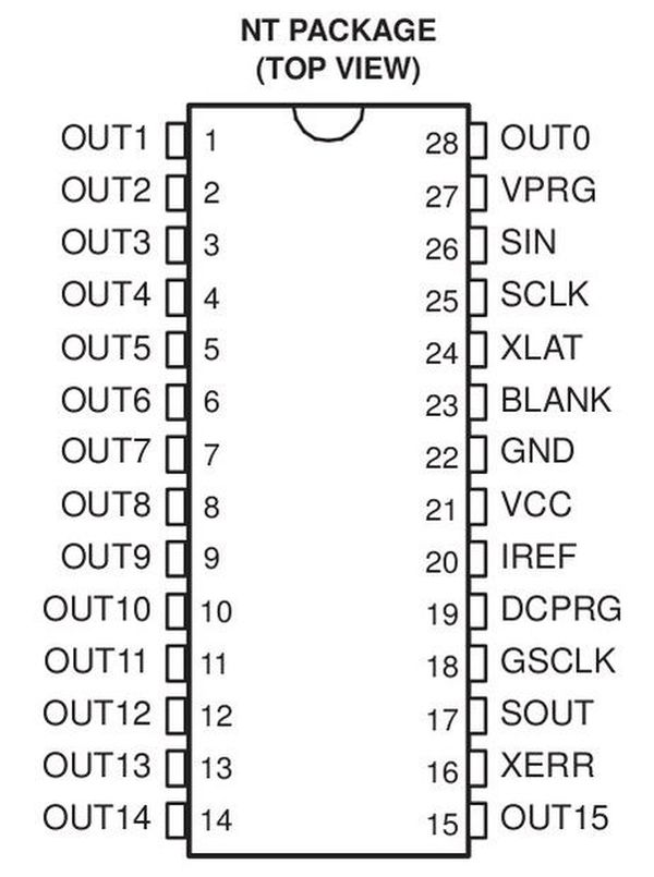
TLC4940
The TLC5940 has 16 output pins that each pulse 4095 times each duty cycle, as opposed to the Arduino’s 255 per cycle. This allows for much finer dimming and control for time-sensitive projects – perfect for LEDs. Multiple of them can also be linked together to create larger chains of multiplexing control. The video below is an excellent example of how the TLC driver works, and the basics to transfer LED data to the driver. The code used in this project to communicate with the TLC drivers is credited to this video as well. It also explains all the minor adjustments that need to be made to allow it to work properly, such as the Amperage Reference pin:
http://www.youtube.com/watch?v=FehBLNHMlfo
The TLC’s wiring is the same for all additional drivers, with the exception of the signal (SIN and SOUT) pins, which are instead wired in series between each driver. (See Diagram1.)
TLC Data sheet: http://www.ti.com/lit/ds/symlink/tlc5940.pdf
Button Mutliplexing
To wire 18 buttons to the Arduino, creative wiring had to be used. Basically, the grid of buttons connects a power source (one of the Arduino ports) to an analog port (another set of ports). (Diagram2.) Even though multiple buttons are connected to each analog input, only one has power at a time. Its a coordinate system for button recognition. The following link shows this principle, just with LEDs instead of buttons: http://www.instructables.com/file/FMMWU6BH2TJ4FPQ
Arduino Comunication
Due to the fact that the TLCs require precise timing and speed, we dedicated one Arduino for data transfer only. We used an additional one to actually calculate which LEDs need to be which colors. Its basically the same interaction between the Video Card and the CPU – one comes up with what needs to be displayed, and the other transfers that data to the LEDs as fast as possible. This does a great job of reducing flicker, and avoids issues with timing on the program’s part due to the fact that the LED driver Arduino has to readjust its internal clock, which can interfere with the regular tones and delays.
The communication is actually facilitated by the serial Tx and Rx (1 and 0) ports. The Tx port from the control Arduino is connected to the Rx port from the LED Driver Arduino. A library called Easy Transfer is used to make this process painless. Here is the link to the instruction website we used: http://www.billporter.info/2011/05/30/easytransfer-arduino-library/. Just make sure you download the libabrary files and SAVE them to the “C:\Program Files (x86)\arduino\libraries” folder.
For more detail: Arduino Controlled RGB LED Dot Matrix Board
- How do you solder wire to aluminum foil?
You must hold the braided wire on the foil while heating it with a soldering iron; adding solder while the wire is connected creates a solid bond since solder does not attach directly to foil. - What is the purpose of the foam in the button assembly?
The foam allows the button to return to its original state after being stepped on and contains cutouts that let the LED light show through to the plexiglass. - Why are two Arduino Uno boards used in this project?
One Arduino calculates which LEDs need specific colors while the second handles the high-speed data transfer to the drivers, reducing flicker and timing issues. - Does the project require multiplexing for the buttons?
Yes, creative wiring connects the button grid so that only one button has power at a time across multiple analog inputs to recognize coordinates. - Can multiple TLC5940 chips be linked together?
Yes, multiple chips can be linked in series by connecting the signal output of one driver to the signal input of the next to create larger chains of control. - What library is recommended for communication between the Arduinos?
The Easy Transfer library is used to facilitate painless serial communication between the Tx port of the control Arduino and the Rx port of the driver Arduino. - How many holes are drilled into the plywood board?
A total of 24 holes are drilled, including 18 for the wires coming from the buttons and 6 additional holes for the LEDs. - What type of wire is suggested for connecting the RGB LEDs?
Simple telephone wire is suggested because it is stranded, making the behind-the-scenes wiring easier and neater.