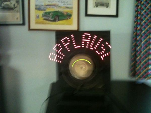
I saw these POV(Persistence of Vision) devices on other Instructables and thought I would like to make one and I have always wanted my own “APPLAUSE” sign. Next improvement will be to make it go on whenever I enter the room. 🙂 Maybe have it say, “And here’s Charlie !” But that is for another time.
So I got a fan at a garage sale, did some reading , found some code and below is a video of my machine in action.
I started with nice code from an Instructable by Scott Mitchell – “Arduino Bike POV” but what I ended up with is his code greatly parred down. I could not get it to work at first and so I keep changing the code . Turned out my problem had nothing to do with the code. So I am going to go back to his code and try again as his is much more generic and would work more easily with different phrases. But that is for later also.
The video below shows the POV in action. It does not seem as broken or disconnected in real life as it does on the video.
Items used in this project:
small fan – garage sale – 2.00
misc lumber – my basement – 0.00
a length of plastic 15 by 2.5 inches – my basement – 0.00
an Arduino – I use a Ardweeny from SolarBotics – about 10.00
7 red LEDs – already had – 1.00
7 – 330 ohm resistors – 3.00
Halls Sensor – I got from Adafruit – US5881LUA – 2.00
1 10k resistor to be used with the Halls sensor – 1.00
2 magnets from local hobby store – 1.00
also will need : wire, 9v battery , screws, Loctite 5 min epoxy, small PCB from Radio Shack
Step 2: Begin Assembly
1. Cut a small – 3 by 5 – piece of 1/4 inch plywood and epoxied to the fan hub . Right now the epoxy is the only thing holding the LED assembly to the fan. Perhaps some wire ties for safety would be good. I think I will add them later.
2. I cut a 15 by 2.5 inch piece of plastic from some stock I had. Sheets of plastic can be had at Home Depot. I just guessed at the size and it turned out to be pretty good.
3. Drill 7 holes in one end about 3/4 of an inch apart for the LEDs. I found a drill size that allows the LEDs to be pressed into the holes quite tightly. If they had not fit nicely, I would have used a dab of hot glue to hold in place.
4. Insert the 7 LEDs into the holes.
5. Attach the plastic to the 3 by 5 plywood with small wood screws.
Step 3: Finish the fan holder
This will depend of the fan you use. I cut a notch out of a piece of 1 by 6 and was able to insert the back of the fan into the notch and then used wire tie to secure the fan to the board. I needed to raise the whole unit so I used a couple of 1 by 3 s to bring the fan up to where it would not hit the base board. I added a piece of plywood to the back so the effect could be better seen. I then painted everything black.
Step 4: Ardweeny & LEDS
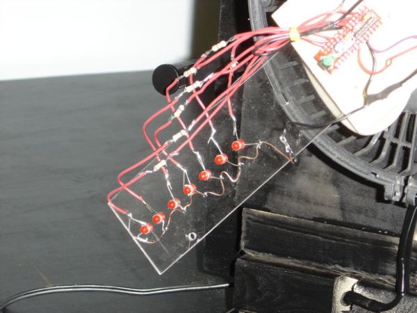
The Ardweeny from Solarbotics comes in a kit and it requires about 30 minutes to solder the pieces together. It is intended to be used on a breadboard and after I have bread boarded the circuit, I solder it to a small piece of PCB board which I can in turn attach to the plywood . The Ardweeny will spin along with the LEDs.
After the Ardweeny is constructed, it is time to wire up the LEDs. I used a bare copper wire as a common ground wire. Each of the short wires from the LEDs is soldered to the copper wire and then the copper wire is connected to a ground on the Ardweeny. From the longer, positive leg, of the LED attach a wire to the Ardweeny and include a 330 ohm resistor in the circuit.
I connected the LEDs to pins 1,2,3,4,5,6,7 with the outer most LED being connected to pin 1.
After all connections are made, attach the Ardweeny to the plywood. I used a small screw thru the PCB.
Step 5: Halls Sensor & Battery
Hall Sensor:
Attach the Halls Sensor to the end of the plastic . I first soldered the sensor to a small piece of PCB and then attached the PCB to the plastic with a small screw.
To connect the sensor I used the following information which I got at Adafruit: “Runs at 3.5V up to 24V. To use connect power to pin 1 (all the way to the left), ground to pin 2 (middle) and then a 10K pull up resistor from pin 3 to power. Then listen on pin 3, when the south pole of a magnet is near the front of the sensor, pin 3 will go down to 0V. Otherwise it will stay at whatever the pullup resistor is connected to. Nothing occurs if a magnet’s north pole is nearby (unipolar).”
Magnet for the sensor:
I attached a small magnet to the end of a dowel and attached the dowel to the fan support. I did this on both sides of the fan. It is important that one of the magnets has its south side facing out and the other magnet has its north side out.
idea: This sensor is a latch type so it is either a 1 or a 0. When the spin begins, the first magnet will turn the LEDS on and when it gets to the other magnet, it will turn them off. Of course this is in concert with the software.
For more detail: Arduino + LEDs + fan = POV “APPLAUSE” sign